
Summary of Contents for GRUP ARGE SVC 5
- Page 1 SVC Drivers User Manual ADDRESS : İkitelli OSB Mah. Çevre 14. Blok Sok. Telas Blok Exterior Door No: 1 Floor: 1-2 Başakşehir/Istanbul info@gruparge.com Tel: +90 212 438 80 24 Fax: +90 212 438 80 25 Version 19-2 1...
- Page 2 1. SELECTION TABLE ................. 4 2. CONNECTION DIAGRAM ..............5 3. TECHNICAL PICTURES ..............6 3.1 SVC 5 Technical Picture ..............6 3.2 SVC 10 Technical Picture.............. 6 3.3 SVC 20 Technical Picture .............. 7 3.4 SVC 30 Technical Picture .............. 7...
- Page 3 SVC Drivers User Manual PROPER USE AND SAFETY REQUIREMENTS Cut all the power when connecting and disconnecting the device to a panel. Do not clean the device with a solvent or similar material. Only use a dry cloth. Please do not intervene to the device when a technical problem is encountered and get in contact with a technical service within the shortest time.
- Page 4 Temperature (Width-Length-Depth) Voltage (A) * Load (V DC) (⁰C) (230 V) (Irms) SRM 1,0 SVC 5 (-10 ─ +55) 230 V 50 Hz 3 x 1,6 kVAr 7,2 A 12 V 103 x 83 x 101 (GA2101) SRM 1,5 SVC 10 (-10 ─...
- Page 5 The SVC 5 and SVC 10 models do not require thermal should be installed vertically with phase input control since they are not needed. When SVC 5 and SVC 10 are and output above. In this case, the trigger used, it is sufficient to short circuit points A and B in the diagram.
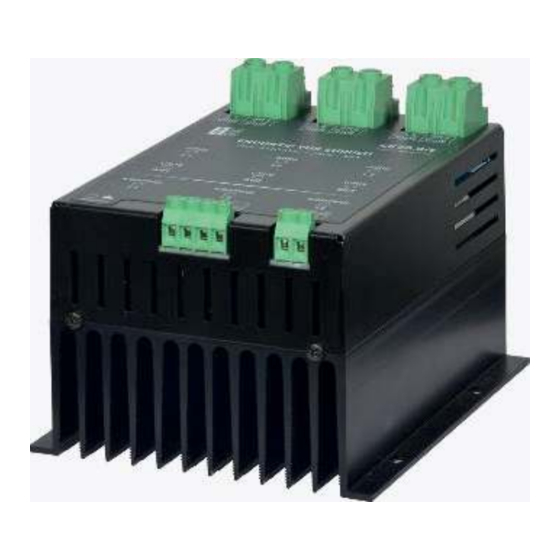
- Page 6 SVC Drivers User Manual 3. TECHNICAL PICTURES 3.1 SVC 5 Technical Picture FRONT VIEW SIDE VIEW TOP VIEW 3.2 SVC 10 Technical Picture TOP VIEW SIDE VIEW FRONT VIEW...
- Page 7 SVC Drivers User Manual 3.3 SVC 20 Technical Picture FRONT VIEW SIDE VIEW TOP VIEW 3.4 SVC 30 Technical Picture TOP VIEW FRONT VIEW SIDE VIEW...
Need help?
Do you have a question about the SVC 5 and is the answer not in the manual?
Questions and answers