
Related Manuals for WELDING INDUSTRIES WELDARC 200 DC


Summary of Contents for WELDING INDUSTRIES WELDARC 200 DC
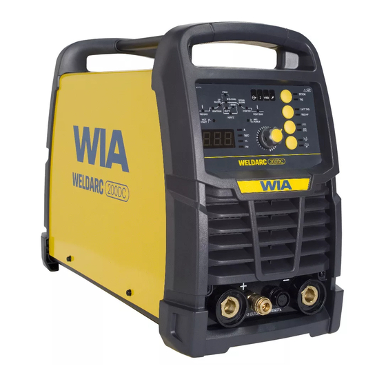
- Page 1 Stick/TIG Welder OPERATORS MANUAL | MC113-0 From serial numbers M1132A* WELDING.COM.AU...
- Page 2 WELDING INDUSTRIES AUSTRALIA A Division of ITW Australia Pty Ltd ABN: 63 004 235 063 1300 300 884 Email: info@welding.com.au welding.com.au WELDWELL NEW ZEALAND A Division of ITW New Zealand NZBN: 9 429 039 833 129 GST NO: 080177186 0800 9353 9355 Email: info@weldwell.co.nz...
-
Page 3: Table Of Contents
CONTENTS Section General Information Page Safe Practices Introduction Receiving Features Specifications Controls Installation Basic Welding Information General Maintenance External Trouble Shooting Trouble Shooting Chart Service Information 11.1 Circuit Diagram Assembly & Parts List Power Source Assembly & Parts List Torch Australian Warranty Information New Zealand Warranty... -
Page 4: Safe Practices
Weldarc 200 DC | Operator Manual | Model No MC113-0 SAFE PRACTICES WHEN USING WELDING EQUIPMENT READ FIRST The information contained in this These notes are provided in the interests manual is set out to enable you of improving operator safety. They should... - Page 5 Burn protection that emit fumes should not be heated unless coating is removed from the work The welding arc is intense and visibly bright. surface, the area is well ventilated, or the Its radiation can damage eyes, penetrate operator wears an air-supplied respirator. light-weight clothing, reflect from light- Work in a confined space only while it is coloured surfaces, and burn the skin and...
- Page 6 Weldarc 200 DC | Operator Manual | Model No MC113-0 Walls touching combustibles on opposite Shock Prevention sides should not be welded on or cut. Walls, Exposed conductors or other bare metal ceilings, and floor near work should be in the welding circuit, or ungrounded protected by heat-resistant covers or shields.
-
Page 7: Introduction
1 INTRODUCTION Unicord 312, Classification ES312-16 MMAW (Stick Welding) A high tensile, chromium nickel electrode Manual Metal Arc Welding (MMAW) is a specially formulated for joining all alloy process where an arc is struck between a steels and irons, and for tool and die flux-coated consumable electrode and the maintenance. -
Page 8: Receiving
Weldarc 200 DC | Operator Manual | Model No MC113-0 2 RECEIVING VRD Disabled Check the equipment received against the shipping invoice to make sure the shipment The open circuit output voltage is maximum is complete and undamaged. If any damage Volts DC. -
Page 9: Specifications
4 SPECIFICATIONS Manufactured to Australian Standard AS60974-1 IEC60974-10 6.3.2 6.3.3. Term Value Unit Rated Input Voltage 220 - 240 Power Frequency 50/60 Rated Input Capacity Generator Capacity 8-10 Rated Maximum Supply Current Imax Maximum Effective Supply Current Ieff Output No Load Voltage Supply Main Circuit Breaker Supply Cable 2.5mm2 &... - Page 10 Weldarc 200 DC | Operator Manual | Model No MC113-0 4 SPECIFICATIONS (CONT.) Term Value Unit Insulation Degree Cover Protection Degree IP23S Weight Shipping Weight Dimension L × W × H 500 x 215 x 345 Shipping Dimension L × W × H...
-
Page 11: Controls
5 CONTROLS Power Switch Located on the rear panel Fig 1 Weldarc 200 DC Controls VRD Safe Mode Indicator Over Temperature Indicator When the machine is in MMA stick mode This light will come on if any internal thermal the light will be on when the voltage across... - Page 12 Weldarc 200 DC | Operator Manual | Model No MC113-0 5 CONTROLS 3 Power On 4.2 4 Step This light will be on when the input supply is In this mode the torch trigger switch turned on. is pressed to start the arc.
- Page 13 Adjustment Knob TIG Start Mode This knob is used to adjust welding Use This mode to select between High parameters. Frequency (HF) start, or LIFT TIG start. The knob primary function is to adjust the High Frequency (HF) arc start is welding current.
- Page 14 Weldarc 200 DC | Operator Manual | Model No MC113-0 5 CONTROLS Fig 4 Weldarc 200 DC Welding Parameters 10 Welding Parameters 10.4 Welding Current Press Adjustment Knob (5) to access The setting for actual weld current. welding parameters. 10.5 Pulse Welding 10.1 Pre Gas...
- Page 15 10.5.4 Base Current 10.6 Arc Force Set the Base current Amps when in When machine is in Stick MMA mode, pulse mode. The Base Current can selecting the ARC FORCE allows be adjusted to 10 to 95% of the Peak adjustment of the increase in current Current.
- Page 16 Weldarc 200 DC | Operator Manual | Model No MC113-0 5 CONTROLS 12 Remote Control Adjustment 12.2 Foot Control for remote control adjustment The output current of the machine can be controlled remotely by On/ Off trigger The WIA foot control (part number...
-
Page 17: Installation
6 INSTALLATION Variation in circuit breaker thresholds. Connection to Electrical Mains Power Supply Ambient temperature. The Weldarc 200DC is fitted with a 15 Amp Number of previous circuit breaker plug, recognisable by a wide earth pin. operations. Power supply authorities require that Actual weld conditions, resulting in equipment fitted with a 15 Amp plug shall higher weld currents. -
Page 18: Basic Welding Information
Weldarc 200 DC | Operator Manual | Model No MC113-0 7 BASIC WELDING INFORMATION Stick Welding (MMAW) Select an appropriate welding current for the electrode diameter by setting the knob Connection for Stick Welding on the machine front panel. WIA AUSTARC electrodes will give the best results. - Page 19 7 BASIC WELDING INFORMATION Electrode TIG TIG Welding (GTAW) Thoriated Tungsten electrodes are normally Connection for TIG Welding used for DC welding current. For TIG Welding, the TIG torch is connected Tungsten Electrode Preparation to the negative terminal. Figure 7 illustrates the correct connection of the welding torch The tungstens needs to be ground to a and gas supply.
- Page 20 Weldarc 200 DC | Operator Manual | Model No MC113-0 Tungsten Current Ranges Electrode Filler Wire Diameter (mm) Cup Size Current Amps Diameter (mm) 15-80 70-150 1.6-2.4 150-250 2.4-3.2 30° Safety Consideration Thoritated Tungsten. Thoriated Tungsten contains the 30° element Thorium (Th). Thorium is a...
- Page 21 7 BASIC WELDING INFORMATION TIG Welding Operation LIFT TIG Operation Connect the Work Clamp to the work piece. When the Welding mode is set to LIFT TIG then the arc start can be achieved with the Turn on the power switch located on the rear following procedure.
-
Page 22: General Maintenance
Weldarc 200 DC | Operator Manual | Model No MC113-0 8 GENERAL MAINTENANCE 9 EXTERNAL TROUBLE SHOOTING Before removing the power source If you are in Australia and the covers, ENSURE that the equipment following checks do not identify is disconnected from the mains the fault condition, the equipment power supply. -
Page 23: Trouble Shooting Chart
10 TROUBLE SHOOTING CHART Problem Likely Reason Outcome All Inverter Multi-Process Models No welding current, no The machine is not turned on If confirmed that the machine display. at both the mains supply and is switched on correctly, the machine power switch. test the same outlet using a known serviceable appliance. - Page 24 Weldarc 200 DC | Operator Manual | Model No MC113-0 Problem Likely Reason Outcome MMA/STICK Models In MMAW (Stick), the arc The technique required The technique to strike is difficult to strike. for VRD enabled welding should be reviewed, not as machines is not the same as a ‘strike’...
-
Page 25: Service Information
11 SERVICE INFORMATION If the welding machine requires If the supply cable is damaged it service or repair, take the machine must be replaced by the manufacturer, to an authorized service agent. their service agent or a similarly qualified person. Australian service agents can be located on the welding.com.au website. -
Page 26: Circuit Diagram
Weldarc 200 DC | Operator Manual | Model No MC113-0 11.1 CIRCUIT DIAGRAMS – POWER SOURCE Fig 13 Weldarc 200 DC Circuit Diagram... -
Page 27: Power Source
12 ASSEMBLY & PARTS LIST - WELDARC 200DC POWER SOURCE Fig 14 Weldarc 200 DC Power Source Assembly... - Page 28 Weldarc 200 DC | Operator Manual | Model No MC113-0 WELDARC 200DC PARTS LIST Item # Part # Description M0109 Handle PAN178 Metal Cover PWA098 Emc Filter Board PWA077 IGBT Inverter Board PWA078 High Frequency Board M0110 Front Plastic Panel...
-
Page 29: Assembly & Parts List Torch
13 ASSEMBLY AND PARTS LIST – TORCH Part # Description 10N31 Collet Body 1.6mm 10N32 Collet Body 2.4mm 10N28 Collet Body 3.2mm 10N23 Collet 1.6mm 10N24 Collet 2.4mm 10N25 Collet 3.2mm 10N50 Ceramic Nozzle Size 4 (6mm) 10N49 Ceramic Nozzle Size 5 (8mm) 10N48 Ceramic Nozzle Size 6 (10mm) 10N47... -
Page 30: Australian Warranty Information
Weldarc 200 DC | Operator Manual | Model No MC113-0 14 AUSTRALIAN WARRANTY INFORMATION Any handling and transportation costs (and other expenses) incurred in claiming under this warranty are not covered by this warranty and will not be borne by Welding Industries of Australia. - Page 31 Warranty provided by: Welding Industries of Australia (ABN 63 004 235 063) A Division of ITW Australia Pty Ltd 5 Allan Street, Melrose Park...
-
Page 32: New Zealand Warranty Information
Weldarc 200 DC | Operator Manual | Model No MC113-0 15 NEW ZEALAND WARRANTY INFORMATION WIA Weldmatic MIG & Weldarc MMA Equipment 3 Year Gold Shield Warranty Statement Effective 1st January 2022 In the event of defects listed in the... - Page 33 NOTES:...
- Page 34 Weldarc 200 DC | Operator Manual | Model No MC113-0 NOTES:...
- Page 35 NOTES:...
- Page 36 WELDING INDUSTRIES WELDWELL AUSTRALIA NEW ZEALAND A Division of ITW Australia Pty Ltd A Division of ITW New Zealand ABN: 63 004 235 063 NZBN: 9 429 039 833 129 GST NO: 080 177 186 1300 300 884 Email: info@welding.com.au 0800 9353 9355 welding.com.au...
Need help?
Do you have a question about the WELDARC 200 DC and is the answer not in the manual?
Questions and answers