Advertisement
Quick Links
FOLLOW INSTRUCTIONS CAREFULLY TO PREVENT PERSONAL INJURY AND/OR DAMAGE TO THE FAN UNIT OR COMPONENT!
ALWAYS DISCONNECT ONE OF THE BATTERY CABLES OR REMOVE POWER FUSES FOR A CIRCUIT WHEN INSTALLING AN
ELECTRICAL FAN OR COMPONENT!
NOTE: Do not remove label from underside of shroud as this will void the products
limited warranty.
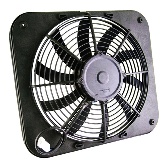
NOTE: The fans contained in this assembly are assembled in puller configuration from
the factory. While these fans can be reversed to be pusher fans, We do not recommend
using this assembly as pusher fans on the front side of the radiator due to the large
amount of ram air that is blocked by the shroud. Fans used as pushers should only be
used as a last resort when there are no other options for mounting.
NOTE: We DO NOT recommend the use of nylon tie kits or any other "through core"
mounting methods for this fan assembly. The motor used in this fan assembly is too
heavy and produce too much starting torque to be supported by the radiator fins.
We recommend using a prefabricated mounting kit MFA107 (included) or fashioning
metal brackets that will attach to at least four of the six ¼ - 20 nylon reinforced nuts
pressed in the back of the shroud and then bolted to the U-channels of the radiator/heat
exchanger (See Fig 1.). 1" X ¼-20 bolts are recommended to attach the brackets to the
shroud. Bolts must NOT be long enough to contact the radiator/heat exchanger. See
Fig 2 on page 2 for bolt pattern.
SEE JETSREME WIRING INSTRUCTIONS FOR WIRING INFORMATION
JETSTREME I
SPECIFICATIONS
LL HEAVY DUTY MOTOR
AIR FLOW @ 0" STATIC
SIZE
DEPTH (WITH SEAL)
AMP DRAW
Page 1 of 2
JETSTREME I & II MOUNTING INSTRUCTIONS
MJS13K
MJS16K
130 W
160 W
1,155 CFM
1,300 CFM
13.5" w x 15" h
13.5" w x 15" h
3.31"
3.70"
7.2
12.4
MARADYNE
4540 W. 160th Street • Cleveland, OH 44135 • Ph: (800) 403-7953 • Fx: (216) 362-6342 • www.maradyneHP.com
© 2023 MARADYNE
QUANTITY
MOUNTING BRACKETS
¼" -20 x 1.25 L
JETSTREME II
MJS12KPS
MJS23K
225 W
(2) 130 W
1,700 CFM
2,310 CFM
13.5" w x 15" h
26" w x 15" h
4.02"
3.31"
14.7
7.2
High Performance Fans
®
High Performance Fans - All rights reserved
®
Package Contents
DESCRIPTION
4
Mounting Brackets
4
¼" – 20 x 1.25 Hex Bolts
¼˝−20 X 1.25 HEX BOLTS
MOUNTING
BRACKET
(4)
HEX BOLT
(4)
1.25
[31.75]
BRACKET INSTALLED
MJS26K
MJS22K
(2) 160 W
(2) 225 W
2,600 CFM
3,100 CFM
26" w x 15" h
26" w x 15" h
3.70"
4.02"
12.4
14.7
TA9001105 REV 6 011023
MFA107
1.5
[38.1]
5.5
[139.7]
Fig 1
MJS22KPS
(2) 225 W
3,400 CFM
26" w x 15" h
4.02"
14.7
Advertisement

Summary of Contents for Maradyne JETSTREME I
- Page 1 MFA107 JETSTREME I & II MOUNTING INSTRUCTIONS FOLLOW INSTRUCTIONS CAREFULLY TO PREVENT PERSONAL INJURY AND/OR DAMAGE TO THE FAN UNIT OR COMPONENT! ALWAYS DISCONNECT ONE OF THE BATTERY CABLES OR REMOVE POWER FUSES FOR A CIRCUIT WHEN INSTALLING AN ELECTRICAL FAN OR COMPONENT!
- Page 2 MFA107 JETSTREME I & II MOUNTING INSTRUCTIONS (CONTINUED) JETSTREME I Fig 2 JETSTREME II MARADYNE High Performance Fans ® 4540 W. 160th Street • Cleveland, OH 44135 • Ph: (800) 403-7953 • Fx: (216) 362-6342 • www.maradyneHP.com Page 1 of 2 TA9001105 REV 6 011023 ©...
Need help?
Do you have a question about the JETSTREME I and is the answer not in the manual?
Questions and answers