Table of Contents
Advertisement
Quick Links
Multiaxis Fiber Optic Acceleration Sensor
The design concepts and engineering details embodied in this manual, which are the property of MICRONOR AG
and MICRONOR SENSORS, are to be maintained in strict confidence; no element or detail of this manual is to be
spuriously used, nor disclosed, without the express written permission of either MICRONOR AG or MICRONOR
SENSORS. entity. All rights are reserved. No part of this publication may be reproduced, stored in a retrieval system,
or transmitted in any form or by any means, electronic, mechanical, photocopying, recording, or otherwise, without
prior written permission from MICRONOR AG or MICRONOR SENSORS.
MR660 Series
System
Instruction Manual
Document: 98-0660-02
Revision: A
Notice of Proprietary Rights
© COPYRIGHT 2022, MICRONOR SENSORS INC.
VENTURA, CA, USA
For Authorized Sales & Support in North America:
MICRONOR SENSORS, INC.
2085 Sperry Ave, Suite A-1
Manufacturer and Worldwide Sales & Support:
Ventura, CA 93003 USA
+1-805-389-6600
sales@micronor.com
www.micronor.com
MICRONOR AG
Pumpwerkstrasse 32
CH-8105 Regensdorf
Switzerland
+41-44-843-4020
sales@micronor.ch
www.micronor.ch
Advertisement
Table of Contents

Summary of Contents for Micronor sensor MR660 Series
- Page 1 The design concepts and engineering details embodied in this manual, which are the property of MICRONOR AG and MICRONOR SENSORS, are to be maintained in strict confidence; no element or detail of this manual is to be spuriously used, nor disclosed, without the express written permission of either MICRONOR AG or MICRONOR SENSORS.
-
Page 2: Revision History
MICRONOR SENSORS MR660 Series FO Acceleration Sensor System Revision History Date Technical Notes Representative 10/26/2022 DNH Original Release Page 2 of 21... -
Page 3: Table Of Contents
MICRONOR SENSORS MR660 Series FO Acceleration Sensor System Table of Contents Revision History ......................2 Product Description ..................... 5 MR660 Fiber Optic Acceleration Sensor Product Family ........ 5 How the MR660 FO Acceleration Sensor Works ..........7 Initial Preparation ....................9 Unpacking and Inspection ................ - Page 4 MICRONOR SENSORS MR660 Series FO Acceleration Sensor System Figures Figure 1. MR660 Series Fiber Optic Acceleration Sensor – Available in 1/2/3 Axis ..5 Figure 2. MR660 1-Axis Sensor System – Signal Conditioner + Sensor ....... 6 Figure 3. MR660 2-Axis Sensor System – Signal Conditioner + Sensor ....... 6 Figure 4.
-
Page 5: Product Description
Product Description MR660 Fiber Optic Acceleration Sensor Product Family Micronor’s MR660 series fiber optic acceleration sensors are based on an opto-mechanical acceleration sensor. Depending on the number of axis, there is a dedicated sensor and signal conditions depending on the number of axes – 1, 2 or 3. Where required, fiber optic extension cables are also available for extended distances. -
Page 6: Figure 2. Mr660 1-Axis Sensor System - Signal Conditioner + Sensor
MICRONOR SENSORS MR660 Series FO Acceleration Sensor System Figure 2. MR660 1-Axis Sensor System – Signal Conditioner + Sensor Figure 3. MR660 2-Axis Sensor System – Signal Conditioner + Sensor Page 6 of 21... -
Page 7: How The Mr660 Fo Acceleration Sensor Works
Figure 4. MR660 3-Axis Sensor System – Signal Condtioner + Sensor How the MR660 FO Acceleration Sensor Works Micronor AG’s MR660 series multiaxis fiber optic acceleration sensors are based on an opto- mechanical acceleration sensor. As shown in Figure 5, the sensing device is a micromechanical silicon mirror (MEMS) which deflects a light beam proportional to the acceleration. -
Page 8: Figure 6. Block Diagram Of The Mr660 Signal Conditioner Per Axis
MICRONOR SENSORS MR660 Series FO Acceleration Sensor System housing is available in aluminum, stainless steel or ceramic material (MACOR). No epoxy is present in the optical path. This ensures an outstanding long term stability. The block diagram of Figure 6 shows the inner workings of the signal conditioner module per axis. -
Page 9: Initial Preparation
Account for and inspect each item before the carton is discarded. In the event of a damaged instrument, write or call your nearest MICRONOR AG local representative or Micronor AG headquarters in Switzerland. -
Page 10: Warranty Information
Warranty Information Warranty MICRONOR AG warrants this product to be free from defects in material and workmanship for a period of 1 (one) year from date of shipment. During the warranty period, we will, at our option, either repair or replace any product that proves to be defective. -
Page 11: Installation And Operation
MICRONOR SENSORS MR660 Series FO Acceleration Sensor System Installation and Operation Mounting the Sensor Unit The sensor unit should be securely fastened to the surface or object being monitored so as not to affect the vibration characteristic being monitored. One method is to design a mechanical bracket which securely fastens the sensor to the DUT (device under test). -
Page 12: Mounting Signal Conditioner Module
MICRONOR SENSORS MR660 Series FO Acceleration Sensor System Mounting Signal Conditioner Module The MR661 series Signal Conditioners are design to mount on standard 35mm DIN rail. Consult Figure 9 below on securing module to DIN rail. Figure 9. Mounting Signal Conditioner to 35mm DIN Rail... -
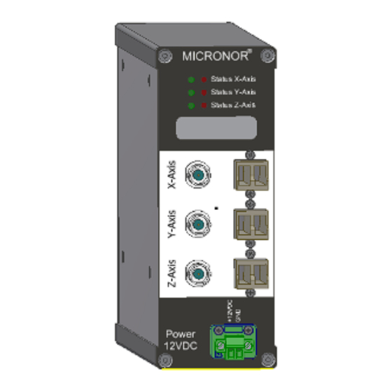
Page 13: Figure 10. Electrical And Optical Connections To The Signal Conditioners
MICRONOR SENSORS MR660 Series FO Acceleration Sensor System Figure 10. Electrical and Optical Connections to the Signal Conditioners Page 13 of 21... -
Page 14: Sensor Optical Connection To The Signal Condition
If power is applied and sensor is operating correctly, the front panel status LEDs should be all green. Red LED represents either damaged sensor or optical connection for that channel. If Red LED, contact Micronor for further instructions. Teach Pendant connection (optional) only applies to 1- and 2- Axis Signal Conditioners. -
Page 15: Specifications
MICRONOR SENSORS MR660 Series FO Acceleration Sensor System Specifications 1-Axis System (MR660-1 Signal Conditioner + MR661/MR662 Sensor) Sensor Note: All electrical connections shall not exceed 3 meters Immunity 100% passive design No. of Axis 1, X (axial) Max frequncy 1100 Hz, minimum... -
Page 16: 2-Axis System (Mr660-2 Signal Conditioner + Mr663 Sensor)
MICRONOR SENSORS MR660 Series FO Acceleration Sensor System 2-Axis System (MR660-2 Signal Conditioner + MR663 Sensor) Sensor Note: All electrical connections shall not exceed 3 meters Immunity 100% passive design No. of Axis 2, Y and Z Max frequncy 1100 Hz, minimum... -
Page 17: 3-Axis System (Mr660-3 Signal Conditioner + Mr664 Sensor)
MICRONOR SENSORS MR660 Series FO Acceleration Sensor System 3-Axis System (MR660-3 Signal Conditioner + MR664 Sensor) Sensor Note: All electrical connections shall not exceed 3 meters Immunity 100% passive design No. of Axis 3, X and Y and Z Max frequncy... -
Page 18: Response Curves
MICRONOR SENSORS MR660 Series FO Acceleration Sensor System Response Curves Figure 11. Typical Sensor Linearity over acceleration range at different frequencies Figure 12. Typical Frequency Response Page 18 of 21... -
Page 19: Mechanical Reference Drawings
MICRONOR SENSORS MR660 Series FO Acceleration Sensor System Mechanical Reference Drawings MR660-1 1-Axis Signal Conditioner MR660-2 2-Axis Signal Conditioner MR660-3 3-Axis Signal Conditioner Page 19 of 21... -
Page 20: Mr661 1-Axis Round Sensor
MICRONOR SENSORS MR660 Series FO Acceleration Sensor System MR661 1-Axis Round Sensor MR662 1-Axis Rectangular Sensor Page 20 of 21... -
Page 21: Mr663 2-Axis Rectangular Sensor
MICRONOR SENSORS MR660 Series FO Acceleration Sensor System MR663 2-Axis Rectangular Sensor MR664 3-Axis Rectangular Sensor Page 21 of 21...
Need help?
Do you have a question about the sensor MR660 Series and is the answer not in the manual?
Questions and answers