Table of Contents
Advertisement
Quick Links
Color Waveform
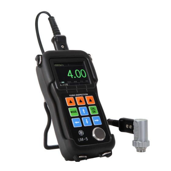
Ultrasonic Thickness Gauge
UM-5 Series
Operating Manual
YUSHI INSTRUMENTS
CONTENT
1.
............................................................................. 1
1.1 Construction of The Gauge ..............................................................2
1.2 Standard Configurations .................................................................. 3
1.3 Optional Configurations .................................................................. 3
1.4 Specifications ...................................................................................4
1.5 Main Fuctions .................................................................................. 5
2.
.............................................................................. 6
3.
............................................................................ 6
3.1 Instrument Calibration .....................................................................6
3.2 Preset Other Specifications ..............................................................9
3.3 Normal Mode .................................................................................13
3.4 A-scan Interface Mode ...................................................................15
3.5 Real Cases Analysis of A-Scan ..................................................... 17
3.6 Operation of B-scan Interface ....................................................... 19
3.6.1 B-scan Display ....................................................................19
3.6.2 Introduction of B-Scan ....................................................... 19
3.7 Dual-echo (Thru-coating) Mode ................................................... 20
3.7.1 A-scan Interface in Dual-echo Mode ................................. 20
4.
........................................................................ 21
4.1 Thickness Value and Waveform Storage ....................................... 21
4.2 Browing The Stored Data .............................................................. 22
5.
5.1 Measuring Error Prevention .......................................................... 22
5.2 Measuring Methods ....................................................................... 23
5.3 Pipe Wall Measurement .................................................................24
5.4 Cast Measurement ......................................................................... 24
6.
...................................................................... 25
6.1 Power Source Inspection ............................................................... 25
6.2 Considerations ............................................................................... 25
6.3 Maintenances ................................................................................. 26
Appendix: Sound Velocities of Common Materrials
.......................................................... 22
....................... 27
Advertisement
Table of Contents

Summary of Contents for YUSHI UM-5 Series
-
Page 1: Table Of Contents
................1 1.1 Construction of The Gauge ..............2 1.2 Standard Configurations ..............3 Ultrasonic Thickness Gauge 1.3 Optional Configurations ..............3 1.4 Specifications ...................4 UM-5 Series 1.5 Main Fuctions .................. 5 Keyboard Functions ................6 Measuring Thickness ................6 3.1 Instrument Calibration ..............6 Operating Manual 3.2 Preset Other Specifications ..............9... -
Page 2: General Introduction 1.1Construction Of The Gauge
1.1Construction of The Gauge General Introduction UM-5 series ultrasonic thickness gauge adopts 2.4 inch color 320*240 dot matrix LCD screen. Launch the ultrasonic through one side of the test material, measure the digitized thickness real-timely, without cutting the object. As a ultraminiature measuring gauge, is researched and developed by our company according to the ultrasonic measuring theory. -
Page 3: Standard Configurations
1.2 Standard Configurations 1.4 Specifications NAME NUMBER Display Type 2.4" color 320 × 240 dot-matrix LCD screen THICKNESS GAUGE Operating Principle Ultrasonic pulse echo and echo- echo method with PROBE dual element transducer PROBE CABLE Measuring Range 0.5mm to 508mm(0.025" to 20.00"), depending on ALKALINE BATTERY material, probe and surface condition RUBBER SHEATH... -
Page 4: Main Fuctions
Measuring Thickness 10. Optional waveform style: outline mode or fill mode 3.1Instrument Calibration 11. Optional rectification mode: RF+, RF-, full wave, half +, half - Before using UM-5 series, the instrument and probe must be calibrated. Language: Chinese, English, German,... - Page 5 4. Dual Echo calibration:Calibrate the velocity from the test block of known 3.1.3 Two point calibration thickness. 5.Setting the velocity manually: If the material velocity is known, for example the velocity of steel is 5900m/s. The sound velocity can be setting manually. 3.1.1 Probe zero calibration Note: The calibration result is 4.00mm, only under the sound velocity of 5900m/S.
-
Page 6: Preset Other Specifications
3.1.5 Velocity adjusting steps 3.1 Velocity adjusting steps Attention 1: Measure the standard block before the calibration, to ensure that the current setting of instrument parameters can measure the standard test block correctly. 3.2 SPECIFICATION ADJUSTING STEPS Attention 2: Probe zero calibration, one point calibration and two point FILE NUMBER –... - Page 7 TC510 (standard probe) TC550 (composite crystal probe) PT-08(standard probe) PT-06(small tube probe) PT-04(miniature probe) GT-12(high-temperature probe) ZT-12 (cast iron probe) NULL(Other probes) 3.3 HALF-WAVE POSITIVE MINIMUM ALARM: Set the minimum thickness alarm value, range of 0.15-635mm. The result will be displayed in red if the actual thickness is less RECTIFICATION WAVEFORM: outline mode and filled mode.
-
Page 8: Normal Mode
3.3 Normal Mode UM-5 series have three measuring interface: normal mode, A-scan interface, B-scan interface. And there are three display modes of normal interface: Thickness value mode, difference/rate-of-reduction measurement mode, MAX. /MIN. measurement mode. Select “VIEW MODE” CONFIGURATION. ATTENTION: When the probe and the object are not completely coupled, the font in the various interfaces are in GREEN, when properly coupled, they are 3.6 DIFFERENCE MODE INTERFACE... -
Page 9: A-Scan Interface Mode
3.4 A-scan Interface Mode GAIN — Adjust the amplification of echo signal by instrument to allow In this mode, users could view the current thickness value and the A-scan manual increase or decrease in ldB. This function is very useful for the testing waveform at the same time. -
Page 10: Real Cases Analysis Of A-Scan
GATE — adjusting the height of the gate.Only when the waveform is higher 2. There are some defects in the testing object, and the gate locks the defect than the gate, the gauge can take the echo and show the value. Attention: this will only show when the GATE specification is highlighted. -
Page 11: Operation Of B-Scan Interface
B-Scan image 11.Parameter display area 12.Gain value 3.6.2 Introduction of B-Scan UM-5 Series thickness gauge has time-base B-scan function. Move the probe along the workpiece surface, then the cross-sectional profile of the workpiece display, use for observe the underside contour of the workpiece. -
Page 12: Data Storage Function
1. Initial-blanking: red blanking line indicated on the screen, starting at zero, 1—storage file name 2—line serial number 3—column serial number so named initial blanking. Waveform with the scope of red strip is invalid, for 4—data in stored 5—back to the previous menu 6—save the current omitted the clutter between the starting point and an echo. -
Page 13: Measuring Methods
90°in the second measurement, the thinner reading is the thickness value. When testing ultra-thin materials, sometimes ‘’double refraction’’ happens, 3. MULTIPLE-POINT MEASUREMENT which is a kind of incorrect result and the result is twice of the real one. When the reading is unstable, measuring several times within a circle with a Another incorrect result called ‘’pulse envelope, cycle jump’’, which means certain point as center and 30mm as diameter, the thinnest reading is the that the testing result is higher than the real one. -
Page 14: Care And Maintenances
4. Keyboard operating is disordered or keyboard doesn’t work. During the usage of the gauge, the current battery power will be shown on As the UM-5 series ultrasonic thickness gauge is high-tech product, the the display, when the battery power is low, the customer should change maintaining work should be made by professional operator and please avoid the batteries promptly so that the measuring accuracy won’t be... - Page 15 Appendix: Sound Velocities of Common Materrials Material Sound Velocity Inch/µS Aluminum 0.250 6300 Alumina Oxide 0.390 9900 Beryllium 0.510 12900 Boron Carbide 0.430 11000 Brass 0.170 4300 Cadmium 0.110 2800 Copper 0.180 4700 Glass(crown) 0.210 5300 Glycerin 0.075 1900 Gold 0.130 3200 0.160...
Need help?
Do you have a question about the UM-5 Series and is the answer not in the manual?
Questions and answers