Table of Contents
Advertisement
Quick Links
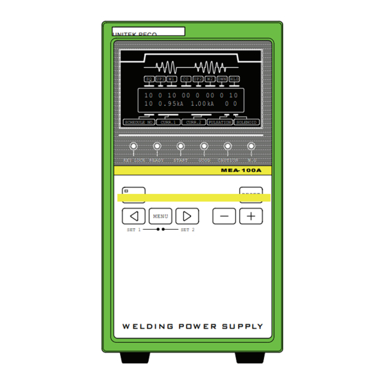
USER'S MANUAL
Revision A
UNITEK PECO
SQ UP1 W1
1 0 0 1 0 0 0 0 0 0 0 1 0
1 0 0 . 9 5kA
SCHEDULE NO.
CURR.1
KEY LOCK
READY
START
WELD
MENU
SET 1
W EL DI N G P OW E R SU P PLY
990-801
March 2003
AC WELDING POWER SUPPLY
UP-100A
OPERATION MANUAL
CO
UP2
W2
DWN
HLD
1.0 0 kA
0 0
CURR.2
PULSATION
SOLENOID
GOOD
CAUTION
N.G
M E A- 1 00A
RESET
SET 2
CONTENTS
1. Special Precautions................. 1-1 to 3
2. Features.................................. 2-1
4. Connection .............................. 4-1
5. Before the Operation ............... 5-1 to 4
6. Basic Operation....................... 6-1 to 11
7. Stepper-Up Function ............... 7-1 to 4
9. Replacing the Battery .............. 9-1
10. Interface.................................. 10-1 to 11
11. Time Chart .............................. 11-1 to 6
12. Troubleshooting....................... 12-1 to 5
13. Specifications .......................... 13-1 to 9
14. Outline .................................... 14-1 to 2
15. Schedule Table........................ 15-1 to 3
Advertisement
Table of Contents

Summary of Contents for Miyachi Unitek UP-100A
-
Page 1: Table Of Contents
USER'S MANUAL 990-801 Revision A March 2003 AC WELDING POWER SUPPLY UP-100A OPERATION MANUAL UNITEK PECO CONTENTS SQ UP1 W1 1 0 0 1 0 0 0 0 0 0 0 1 0 1. Special Precautions....1-1 to 3 1 0 0 . 9 5kA 1.0 0 kA... - Page 2 Copyright © 2003 Unitek Miyachi Corporation The engineering designs, drawings and data contained herein are the proprietary work of UNITEK MIYACHI CORPORATION and may not be reproduced, copied, exhibited or otherwise used without the written authorization of UNITEK MIYACHI CORPORATION. Printed in the United States of America.
-
Page 3: Special Precautions
UP-100A 1. Special Precautions C A U T I O (1) Safety Precautions Before using, read "Safety precautions" carefully to understand the correct method of use. Denotes operations and practices that may result in personal injury or damage to the... - Page 4 UP-100A W A R N I N G Do not put your hands between the electrodes When welding, keep your fingers and hands away from the electrodes. Do not touch any welded part or electrodes during welding and just after welding finished The welded part of a workpiece, electrodes and arm are very hot.
- Page 5 UP-100A (2) Precautions for Handling Install this Welding Power Supply on a firm, level, horizontal surface. If it is inclined, malfunction may result. Do not install this Welding Power Supply in the following : Damp places where humidity is higher than 90%,...
- Page 6 UP-100A 1. Special Precautions...
-
Page 7: Features
UP-100A 2. Features The UP-100A is a single-phase AC resistance-welding power supply designed for fine spot welding. The control method can be selected from secondary constant-current control and power supply voltage fluctuation compensation control. The UP-100A realizes high quality welding, so it is suitable for small size precise welding. - Page 8 UP-100A 2. Features...
-
Page 9: Name And Functions Of Each Section
This LCD panel is used to monitor various UP-100A functions. Indicates various settings and weld measurement results. A [READY] Lamp Lights when the UP-100A is ready to supply a welding current. This lamp is synchronized with Terminal 12 ([READY]) of the I/O Terminal Strip on the rear panel. - Page 10 UP-100A B [KEY LOCK] Lamp If this lamp is lit, the schedules or other settings cannot be edited. However, you can still change screens and the schedule no. using the [MENU] key, and change functions using NP on the SET2 screen (See 8. (2) ).
- Page 11 UP-100A K [MENU] Key Used to move from the MENU screen to another screen or to return to the MENU screen from the SET screen. For the SET screen, see 5. and 8. To move to the SET1 screen, simultaneously press the [ ] key and the [MENU] key.
- Page 12 The other end of the power cable is connected to a single-phase power supply for welding. Circuit Breaker Supplies or shuts off power to the UP-100A. Raise the handle to turn the circuit breaker on and to supply welding power to the UP-100A.
- Page 13 Power Cable Inlet Pass the power cable through this inlet to connect the cable to the power cable connecting terminal. Grounding Terminal Be sure to ground the UP-100A to prevent electric shock. 3. Name and Functions of Each Section...
- Page 14 UP-100A 3. Name and Functions of Each Section...
-
Page 15: Connection
UP-100A 4. Connection The illustration below shows the UP-100A connected to a typical weld head, and a typical welding transformer. 4. Connection... - Page 16 UP-100A 4. Connection...
-
Page 17: Before The Operation
UP-100A 5. Before the Operation (1) Screen Configuration MENU Screen Press the [MENU] key to select the desired screen. The screens are cycled like this: Welding schedule setting screen Current monitor display screen Ordinary Stepper-Up (4 screens) (7 screens) Current monitor range setting screen... - Page 18 (2) Control Method and Welding Current Cycle Settings Follow the procedure described below and set the control method and welding current cycle according to the specific application after the UP-100A is installed. (Secondary constant-current control is factory-set on shipment.) To display the SET2 screen, press the [MENU] key simultaneously and the [ ] key for at least a second.
- Page 19 Weld time. 00–99 cycles The set weld time must be the actual weld time. The set current must be 60% to 90% of the actual welding current in order to prevent the damage to the UP-100A 0.20–9.99kA caused by overcurrent. SOL1 Weld Force number.
- Page 20 UP-100A If the display does not revert to the screen, repeat test welding until the screen returns. (To measure the maximum current, welding must be performed for 6 cycles.) Caution: Moving to another screen during the automatic maximum current setting will interrupt the setting process.
-
Page 21: Basic Operation
6. Basic Operation (1) Supplying Power Turn on the circuit breaker on the rear panel to supply power to the UP-100A. During the startup self-diagnostics, the LCD screen displays the model number and software version. If the self-diagnostics completes without errors, the MENU screen is displayed. - Page 22 UP-100A Item Setting Range/Display a Squeeze (SQ) 00–99 cycles b Upslope 1 (UP1) 0–9 cycles (Upslope 1 is included in Weld 1.) c Weld 1 (W1) 00–99 cycles d Cool (CO) 00–99 cycles e Upslope 2 (UP2) 0–9 cycles (Upslope 2 is included in Weld 2.) Weld 2 (W2) 00–99 cycles...
- Page 23 UP-100A Power Supply Voltage Fluctuation Compensation Control at Multi-Cycle Welding Welding Schedule Setting Set the welding current (n, o) in a percentage to the maximum current expressed as 100% (For the maximum current, see 5. (3).) W e l d F orce...
- Page 24 UP-100A Single-Cycle Welding Welding Schedule Setting Set the welding current (b, e) in a percentage to the maximum current expressed as 100% (For the maximum current, see 5. (3).) W e l d F o r c e W el d i n g C u r r e n t...
- Page 25 UP-100A Half-Cycle Welding Welding Schedule Setting Set the welding current (b) in a percentage to the maximum current expressed as 100% (For the maximum current, see 5. (3).) W e l d F o r c e H ALF W e l d i n g C u r r e n t...
- Page 26 (3) Ready for Welding (Turning on the [READY] Lamp) By following the below, the [READY] lamp lights and the UP-100A is brought into the READY state (to flow the welding current). If any fault occurs, rectify the fault and then clear fault output. (For clear of fault outputs, see 12.
- Page 27 Without parity Select #1–#31 schedules by combining schedule signals [SCHEDULE1], [SCHEDULE2], [SCHEDULE4], [SCHEDULE8] and [SCHEDULE16]. When no schedule is input (all signal circuits are opened), the UP-100A operates with schedule #1. With parity To use the parity function, set SS on the SET2 #1 screen to 1. (See 8. .) Parity check is odd parity.
- Page 28 5-Schedule Input from External To select 5-schedule input, set SS on the SET2 #1 screen to 2. (See 8. .) If no schedule is input (all the signal circuits are opened), the UP-100A operates with schedule #1. If the schedules are input under 2 or more numbers at a time, the schedule under the lower SCHEDULE number is used.
- Page 29 UP-100A (6) Welding (Current) End If the welding is initiated while the welding schedule setting screen is displayed, the screen indicates the measured currents (b and c) and the determination of the welding result (d). (See figure below.) The End signal and the determination of the welding result (Normal (GOOD) signal, Caution (CAUTION) signal and Trouble (NG) signal) are output from the I/O terminal strip.
- Page 30 UP-100A Switching off power clears the monitored currents and the determination. NB: Press any key to move to the welding schedule setting screen. (7) Current Monitor Display Screen The current monitor display screen indicates the welding currents, the weld time and the conduction angle.
- Page 31 UP-100A Half-Cycle Welding ° Item Setting Range/Display a Weld force number Indicates the weld force number used for welding. b HALF current Indicates the effective current in the half-cycle. HALF conduction Indicates the monitored conduction angle in the half- angle cycle.
- Page 32 UP-100A 6. Basic Operation 6-12...
-
Page 33: Stepper-Up Function
UP-100A 7. Stepper-Up Function The stepper-up (-down) function lets you increase or decrease the welding current when the weld count reaches the set value. Increasing the welding current automatically according to wear of the electrode can extend the life of the electrode. (Stepper-up) Use this function for fusing in which the welding current must be reduced to accommodate increased temperatures within an electrode or work pieces. - Page 34 UP-100A (2) Stepper Count and Current Settings The stepper-up (-down) function is performed when the weld count reaches the set value. Stepper-Up Operation Chart C u r r ent [ k A ] Stepper-up compl e t e d S e t c u r r e n t S t e p p e r c o u n t 5 Stepp e r N o .
- Page 35 UP-100A (3) Stepper-Up (-Down) Rate Setting ATTENTION Set the value of “the welding current x the stepper-up rate” so that it does not exceed the following value: The set maximum current (5. (3)) in the secondary constant-current control 99.9% in the power supply voltage fluctuation compensation control When the value over the maximum current is set, the fault code [E09: STEPUP RATE TROUBLE] is given at the input of the start signal.
- Page 36 UP-100A (4) Checking the Stepper-Up Status Use this screen to check the currently operating stepper number and the weld count for each weld force number (solenoid). (This is not a total count from stepper 1.) Press the [MENU] key to go to the Stepper-Up Status Display Screen.
-
Page 37: Detail Settings (Set2 Screen) . 8-1 To
8. Detail Settings (SET2 Screen) Various functions of the UP-100A can be set on the SET2 screen. The UP-100A is factory-set to a set of standard settings. For most applications, no editing of these settings is required. If the settings need to be edited, read this “8. Detail Settings” carefully before attempting to do so. - Page 38 No re-welding carried out. current or the no- Performs re-welding. current Determines how Skips to the next sequence. (Skips the UP-100A to COOL (CO) if WELD1 (W1) is functions when the underway.) WELD SKIP signal Skips to HOLD (HLD). is input...
- Page 39 UP-100A regardless of the 00.5: Ignores errors in the first half-cycle. setting) 01.0: Ignores errors in the first full cycle. (The setting can be changed every half-cycle.) 10.0: Ignores errors in the first 10 cycles. #3 Screen This screen indicates different data according to the welding and control methods selected.
- Page 40 UP-100A 01.0: Ignores the no-current in the first full cycle. (The setting is changeable every half-cycle.) 10.0: Ignores the no-current in the first 10 cycles. 8. Detail Settings (SET2 Screen)
- Page 41 If the toroidal coil is broken or missing, the current is not detected even if it flows actually, therefore the UP-100A tries to flow large current forcedly. As the result, the welding machine is overloaded and may be damaged.
- Page 42 UP-100A Fault Initial Display and Description Setting Definition Code Setting SCR OVERHEATING Trouble (not Thyristor overheating changeable) NO CURRENT Caution Welding current is not detected. (No Trouble current) LOW CURRENT Caution Welding current is below monitor Trouble lower limit. HIGH CURRENT...
-
Page 43: Replacing The Battery
Replace the battery, if necessary. Read the following instructions before replacement. (Battery used: CR2450) The UP-100A retains welding schedules and other settings in memory, even if the battery is removed. However, as a backup measure, complete the schedule table (15. Schedule Table) to provide a record of the settings before removing the battery. - Page 44 UP-100A 9. Replacing the Battery...
-
Page 45: Interface
UP-100A 10. Interface Input and output signals are through the rear panel I/O terminal strip. (1) Connection of External I/O Signals <Also see (C) and (D) in 13. (4) Model No.-Spec Reference Table.> When [SOL.1], [SOL.2], [CAUTION], [STP/WLD END] and [READY] are Transistor... - Page 46 UP-100A When [SOL.1] and [SOL.2] are Relay output (Outputs other than this are same as I/O terminal strip SOL C O M External power supply SOL 1 SOL 2 When [CAUTION], [STP/WLD END] and [READY] are Photo-MOS Relay output (Outputs other than this are same as )
- Page 47 UP-100A (2) Explanation on the External I/O Terminals Terminal Description If the UP-100A is connected to a contact or NPN open collector output-type device (when using the built-in power supply), connect this terminal to terminal 2. [EXT.COM] If the UP-100A is connected to a NPN open collector output (when using an external power supply) or PNP current output-type device, connect this terminal to a 24VDC external power supply.
- Page 48 15-16 [NG] The circuit is closed when [ERR RESET] is input. Note: When the power supply of the UP-100A is off, the circuit is closed. Relay contact output: 24VDC, or 250VAC or less, 0.5A Output terminal for Normal End [GOOD] signal.
- Page 49 UP-100A Input terminal for [WELD ON/OFF] signal. Opened WELD OFF (Shuts off the welding current.) [WELD Closed WELD ON (Flows the welding current.) ON/OFF] For the welding current to flow, the [WELD] key on the front panel must also be ON.
- Page 50 UP-100A Terminal Description Common terminal for input signals. [COM] Input terminal for [START] signal and 1ST STAGE signal. This circuit must be closed to supply a welding current in [READY] mode. The specific operation depends on [SM] setting of the #1 screen in the SET2 screen, as shown below (See 8.
- Page 51 UP-100A (3) Connection of Input Signals Connection to Contact Input Device Use a jumper wire to connect terminals 1 and 2. (Ou t s i d e ) ( I n s i de) EXT. COM +24V Short! INT. 24V O U T...
- Page 52 UP-100A Connection to NPN Open Collector Output Device (when using an external power supply) Connect terminal 1 to the "+" terminal of the external 24VDC power supply. (O u t s i d e ) ( I n s i d e ) + 2 4 V EXT.
- Page 53 UP-100A (4) Connection of Output Signals <See C (Transistor Output or Relay Output) in 13. (4) Model No.-Spec Reference Table.> Connection of SOL1 and SOL2 [Transistor Output] ( I n s i de) (Outsi d e ) + 24V SOL COM...
- Page 54 UP-100A Connection of CAUTION, STP/WLD END, and READY [Transistor Output] ( I n s i d e ) ( O u t s i d e ) INT. 24V OUT CAUTION STP/WLD END READY 24V D C 0 . 1 A...
- Page 55 UP-100A Connection of END, NG and GOOD (Outsi d e ) ( I n s i de) Exter n a l power s u p p l y Exter n a l power s u p p l y Exter n a l...
- Page 56 UP-100A 10. Interface 10-12...
-
Page 57: Time Chart
UP-100A 11. Time Chart (1) Basic Weld Cycle Time Chart S t a r t s i g n a l ( i n p u t ) O F F [ S T A R T ( 1 S T ) ]... - Page 58 UP-100A (2) Start Signal Time Chart Establishing a Welding Schedule The welding schedule is established when the start signal is input and the chattering stabilizing time (SDT) has elapsed. For information on making settings, see 8. (2) . ( A)
- Page 59 UP-100A T1: Time required to start weld force after input of the start signal SM on the SET2 screen is set to 1 (For the setting of SM, see 8. (2) ) The welding sequence runs to completion, even if input of the start signal is stopped after starting W1.
- Page 60 UP-100A SM on the SET2 screen is set to 3 (For the setting of SM, see 8. (2) ) The welding sequence is performed in 2-stage start mode. The Weld Force signal is output when the 1st stage signal is input. Welding begins when the 2nd stage signal is input.
- Page 61 UP-100A (3) End, Normal End and Weld End Signals Time Chart The output time for End, Normal and Weld End signals depends on the setting for the End signal output time (HET). Outputs upon completion of the welding sequence. The output time is the time set for HET (See 8. (2) ).
- Page 62 UP-100A End Signal Output Time (HET) is set to 20 Output for 200ms, not depending on whether the start signal circuit is opened or closed. S t a r t s i g n a l ( i n p u t )
-
Page 63: Troubleshooting
The letter in [ ] at the end of the message indicates the cause of fault. Cause of "C" is displayed when the UP-100A fails to monitor the frequency of fault the welding power supply. A letter other than "C" is displayed when the CPU malfunctions. - Page 64 Cause of The UP-100A is overheated. fault Switch off the UP-100A and leave it to stand to let it cool down. If the UP-100A has cooled down, turn on [ERROR RESET]. Measures The duty cycle may be too high. Make sure that the UP-100A is used at the adequate duty cycle and within the specified operating temperature range.
- Page 65 UP-100A Message FULL WAVE Time of During welding detection The monitored conduction angle exceeds 175° during operation with the power supply voltage fluctuation compensation control. This fault Cause of may occur when it occurred for 3 times or more in the multi-cycle fault welding.
- Page 66 The thyristor short-circuit current is detected during the squeeze. Cause of N.B.: The short-circuit current is not detected when the toroidal coil is fault not connected to the UP-100A. The thyristor may be broken. Ask your nearest Unitek Miyachi Corp. Measures or your distributor for repairs.
- Page 67 UP-100A detection Cause of The [WELD STOP] signal is turned off. fault Measures Input the [WELD STOP] signal and turn on [ERROR RESET]. Output Outputs the trouble [NG] signal when the fault occurs. signal 12. Troubleshooting 12-5...
- Page 68 UP-100A 12. Troubleshooting 12-6...
-
Page 69: Specifications
UP-100A 13. Specifications (1) Specifications Item Specifications Single phase 200V/220V/230V/240V/380V/400V/460V/480VAC Power Supply (Voltage is selectable but factory-fixed on shipment.) +13%, -20%, 50/60Hz 20kVA (Duty cycle: 10% when 200VAC is input) Maximum 26kVA (Duty cycle: 10% when 400VAC is input) Capacity Note: For duty cycle, see 13. - Page 70 UP-100A Item Specifications W eld Force o utput D W N W elding c urrent H L D Single-cycle welding a. Squeeze (SQ): 00–99 cycles b. First half wave (+HALF): 0.5 cycle c. Second half wave (-HALF): 0.5 cycle d. Hold (HLD): 00–99 cycles...
- Page 71 UP-100A Item Specifications Secondary constant-current control Upper limit setting: +1%– +49% Lower limit setting: -1%– -49% Current Monitoring (If set to 00, current monitoring is turned off.) (31 schedules) Power supply voltage fluctuation compensation control Upper limit setting: 0.20–9.99kA (in 10A increment) Lower limit setting: 0.20–9.99kA (in 10A increment)
- Page 72 UP-100A Item Specifications Stepper No.: Stepper 1–5 Stepper-up Stepper-up rate: 50%–150% (in 1% increment) of (2 schedules; SOL1 the set current for Stepper 1 and SOL2) Stepper-up weld count: 0–9999 Production Counter 0–99999999 Schedule (1–31 schedules SCH1, 2, 4, 8, 16...
- Page 73 Cable 100A PK-03294-002 ..5m PK-03294-003 ..10m Note: If you provide a cable, select a cable with the following specification. Output Connects the UP-100A to the Rated voltage: 600V min. Cable welding transformer. Number of cores: Cross section: 5.5mm min.
- Page 74 UP-100A (3) Duty Cycle Power supply 200V, Ambient temperature 35 Duty Cycle [%] Power supply 200V, Ambient temperature 45 Duty Cycle [%] 13. Specifications 13-6...
- Page 75 UP-100A Power supply 400V, Ambient temperature 35 Duty Cycle [%] Power supply 400V, Ambient temperature 45 Duty Cycle [%] 13. Specifications 13-7...
- Page 76 UP-100A (4) Model No.-Spec Reference Table Sub- number Power Terminal Strip Solenoid [CAUTION], [STP/WLD Supply Cover Output END], [READY] Outputs 100A- Voltage L-shaped terminal Transistor 00-00 220V Transistor output strip cover output Full terminal strip Transistor 00-02 480V Transistor output...
- Page 77 UP-100A Sub- number Power Terminal Strip Solenoid [CAUTION], [STP/WLD Supply Cover Output END], [READY] Outputs 100A- Voltage Full terminal strip 00-53 460V Relay output Transistor output cover 13. Specifications 13-9...
- Page 78 UP-100A 13. Specifications 13-10...
-
Page 79: Outline
UP-100A 14. Outline <Find type of your terminal strip cover in (B) of the Model No.-Spec Reference Table in 13. Specifications and refer to corresponding outline.> (1) L-Shaped Terminal Strip Cover 14. Outline 14-1... - Page 80 UP-100A (2) Full Terminal Strip Cover 14. Outline 14-2...
-
Page 81: Schedule Table
UP-100A 15. Schedule Table 15. Schedule Table 15-1... - Page 82 UP-100A 15. Schedule Table 15-2...
- Page 83 UP-100A Count Stepper-Up (-Down) Rate 0000–9999 050%–150% STEP1 STEP2 SOL 1 STEP3 STEP4 STEP5 STEP1 STEP2 SOL 2 STEP3 STEP4 STEP5 Screen Item Range Setting SET1 #1 MAX CURR 0.5–9.9 kA SET1 #2 LCD CONTRAST 01–16 0–1 0–3 SET2 #1 0–3...
- Page 84 UP-100A 15. Schedule Table 15-4...
Need help?
Do you have a question about the UP-100A and is the answer not in the manual?
Questions and answers