Table of Contents

Summary of Contents for Unitrol SOFT TOUCH 9381-34WDS/115
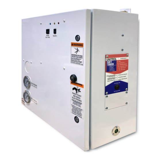
- Page 1 SOFT TOUCH for NON-UNITROL FREQUENCY CONVERTER CONTROLS 9381-34WDS/115, 9381-34WDS/24DC 9381-34YDS/115, 9381-34YDS/24DC UNITROL ELECTRONICS, INC. 702 LANDWEHR ROAD NORTHBROOK, IL 60062 847-480-0115 techsupport@unitrol-electronics.com...
- Page 3 TOUCH system. It is designed to protect your resistance welder operator from serious elec- trode pinch point injury. Having trouble or need answers to your ques- tions? Unitrol supplies free phone support for the life of this and all our products. You can contact us: By Phone: Monday - Friday 9:00 - 5:00 CT: 847-480-0115.
- Page 4 MODEL NUMBER AND OPTIONS AS CHECKED BELOW SERIAL NUMBER: VALVE MODEL TYPE VOLTAGE CYLINDER OR DIAPHRAGM 9381-34WDS/115 115AC HEAVY WEIGHT RAM CYLINDER OR DIAPHRAGM 9381-34WDS/24DC 24DC HEAVY WEIGHT RAM CYLINDER OR DIAPHRAGM 9381-34YDS/115 115AC LIGHT WEIGHT RAM CYLINDER OR DIAPHRAGM 9381-34YDS/24DC 24DC LIGHT WEIGHT RAM...
- Page 5 WARRANTY Unitrol Electronics provides a 5-year limited warranty to cover all of this SOFT TOUCH sys- tem. The warranty periods are determined using the date the new control was originally shipped from Unitrol Electronics. All warranty coverage is FOB Northbrook. Illinois.
-
Page 6: Table Of Contents
TABLE OF CONTENTS VERIFY YOUR SOFT TOUCH SENSOR BOARD IS CORRECT HOW SYSTEM OPERATES INSTALLATION, 9181-34W HEAVY WEIGHT SERIES INSTALLATION OF SCR DRIVER BOARD CONNECTING SCR FIRING CABLE CONNECTING CONTROL CABLE WIRING CONTROL INSTALLING SECONDARY CURRENT PICKUP COIL CONTROL CABLE WIRING CHART HOOKUP FOR 9381-34WDS/115, 9381-34YDS/115 HOOKUP FOR 9381-34WDS/24DC, 9381-34YDS/24DC RETRACT OPTION 9381-34JB3/PMCO... -
Page 7: Verify Your Soft Touch Sensor Board Is Correct
2. SOLENOID VALVE VOLTAGE. Be sure that the two tall relays, K2 and K3, show the same voltage on the top printing as the solenoid voltage of your welding control. If they are not correct, contact Unitrol to swap relays. FOR 115VAC... - Page 8 INSTALLATION Note that this system REPLACES the existing weld solenoid valve. Mount the control in a convenient location using the four mounting tabs on the back of the box. Remove hoses from the existing welding solenoid valve. This solenoid valve will not be used with this this control.
-
Page 9: How System Operates
SOFT TOUCH PINCH POINT PROTECTION SYSTEM FOR INSTALLATION ON NON-UNITROL 3Ø FREQUENCY CONVERTER CONTROLS HOW THE SYSTEM OPERATES When the solenoid valve output from the welding control goes HIGH, this voltage goes to the 9280-TS7 SOFT TOUCH de- tection board, terminal #9. -
Page 10: Installation Of Scr Driver Board
INSTALLATION OF SCR DRIVER BOARD This SOFT TOUCH system is supplied with a separate aluminum heat sink with a high-voltage SCR contactor installed. The SCR contactor is used to drive the transformer windings operated by existing SCR-A during the SOFT TOUCH initial sequence to produce a TRACE signal as explained on page 3. -
Page 11: Connecting Control Cable
SUPPORT tab for hookup charts for some popular welding con- trols. If you do not see your brand and model welding control listed and cannot figure out how to find the point in the welding control that are shown on the next page, contact Unitrol for assistance at:: techsupport@unitrol-electronics.com... - Page 13 INSTALLING SECONDARY PICKUP COIL Put the secondary current pickup coil band around the lower electrode arm as shown in this photo: The band opens at the buckle for easy installation. Note that the buckle is approximately at the bottom and that the coil is as far out of the way as possible so that it is not contacted by parts being welded.
-
Page 14: Wiring Control
WIRING CONTROL CONTROL CABLE WIRING CHART CONNECT IN WELDING CONTROL CONNECT IN WELDING CONTROL FOR WIRE COLOR 24VDC MODELS 115VAC MODELS TERM 9381-34WDS/24DC 9381-34WDS/115 9381-34YDS/24DC 9381-34YDS/115 BLACK 115VAC L 100VAC L - 240VAC WHITE 115VAC N 100VAC N - 240VAC RED/BLACK ST. - Page 15 INSTALLATION HOOK-UP DRAWING FOR 9381-34WDS/115, 9381-34YDS/115...
- Page 16 INSTALLATION HOOK-UP DRAWING 9181-34WDS/24VDC, 9181-34YDS/24DC...
- Page 17 OPTIONAL RETRACT WITH SOFT TOUCH 9381-34JB3/PMCO & 9381-34JB3 The RETRACT function starts when the RETRACT switch is closed and latched. This can be either the first stage of a 3-stage footswitch, or a separate footswitch. This option protects against pinch point injury when bringing the electrodes from fully open RETRACT position to the WORK posi- tion (small space between electrodes).
- Page 18 OPTIONAL RETRACT WITH SOFT TOUCH 9381-34JB3/PMCO & 9381-34JB3 (continued) 3. Typical welders have the RETRACT solenoid valve operated from the welding control. If this matches your welder, skip to the next page. If this signal is not available (unusual), you can connect wiring from either a 3-stage or 1-stage latching footswitch as shown be- low.
- Page 19 OPTIONAL RETRACT WITH SOFT TOUCH 9381-34JB3/PMCO & 9381-34JB3 This hook-up on this page is for RETRACT that uses RETRACT VOLTAGE from the welding control. Leave the exist RETRACT solenoid valve in place and wired to the original welding control terminals. WHITE/BLACK STRIPE WIRE: For controls that operate 115VAC solenoid valves: Connect to 115V N.
- Page 20 OPTIONAL RETRACT WITH SOFT TOUCH 9381-34JB3/PMCO & 9381-34JB3 (continued) PLUMBING: Connect hoses from the input port on the existing RETRACT SOLENOID to the bulkhead on the SOFT TOUCH enclosure as shown below. ADJUST the RETRACT BUCKING REGULATOR until the electrodes close with less than 50 pounds of force.
- Page 21 OPTIONAL TIMED DELAY 9181-34BPA Some materials being welded have coatings or other conditions that prevent good continuity between elec- trodes. For these conditions option #9181-34BPA will allow the welder to be operated using TIMING rather than CONTINUITY to switch from low force to high welding force.
- Page 22 OPTIONAL DEPTH SWITCH 9181-34LSA, 9181-34LSB This option allows use of either CONTINUITY DETECTION or closure of a DEPTH SWITCH to turn on the weld pressure and start the weld sequence. It is useful when parts being welded have a low-conductivity coating. INSTALLATION: 9181-34LSA: Mount the PNP proximity switch that is supplied with this option on the body of the welder using the mounting...
- Page 23 OPTIONAL DEPTH SWITCH 9181-34LSA, 9181-34LSB continued Wire the switch to match the appropriate hookup below. P-N-P P-N-P P-N-P BROWN BLACK BLUE -24IS LEDS -24IS +24IS MECHANICAL LIMIT SWITCH BROWN PNP PROXIMITY SWITCH BLACK BLUE USE IN PRODUCTION: Turn the key counter-clockwise to the CONTINUITY position. The yellow panel indicator will glow.
- Page 24 OPTIONAL DEPTH SWITCH 9181-34LSC This option is a redundant function that allows the start of full weld- ing force only after both electrode continuity AND depth switch clo- sure. It does not include a remote selection switch and is always in place.
- Page 25 PNEUMATIC HOOKUP 9381-34YDS… LIGHT RAM OR ROCKER ARM WELDERS CONNECT HOSES TO PORTS SHOWN BELOW...
- Page 26 PNEUMATIC HOOKUP 9381-34WDS… HEAVY WEIGHT RAM WELDERS CONNECT HOSES TO PORTS SHOWN BELOW...
- Page 27 ADJUSTING THE SOFT TOUCH VALVE SYSTEM F0R 9381-34WDS… SERIES CONTROLS - HEAVY WEIGHT RAMS The ADVANCE PRESSURE puts air on the underside of the air cylinder piston to LIFT the welder ram. This is used to partially lower the force between the elec- trodes due to the dead (gravity) weight of the welder’s ram.
- Page 28 SETTING SOFT TOUCH BOARD MAXIMUM DETECT TIME SWITCHES Locate the four-section ADD FOR DETECT TIME DIPswitch on the left side of each SOFT TOUCH board. This switch is marked: 1, .75, .5, and .25 seconds. Set the switches to a value that is about 2 times how long it will take for the electrodes to close.
-
Page 29: Setting And Testing Electrode Closing Force
SETTING AND TESTING ELECTRODE CLOSING FORCE Turn power on to SOFT TOUCH system. Adjust the pneumatic system to produce safe closing electrode closing force using the directions on page 23 to match the mod- el number of this SOFT TOUCH system. Use the TIP DRESS switch to close the electrodes each time you make a change in the pressure regulator settings. -
Page 30: Setting System Reading Sensitivity
SETTING SYSTEM READING SENSITIVITY The continuity sensing system monitors the conditioned voltage from the flexible secondary current coil. The sensor board starts to monitor this voltage when the welding control sends the solenoid valve voltage to the sensor board to start a weld cycle. At that time, the control is sending a very low% current into the welding transformer primary to generate a low voltage on the welder transformer secondary. -
Page 31: Startup Procedure
STARTUP PROCEDURE 1. Turn on power to welding control. 2. The SOFT TOUCH annunciator panel should go through a test procedure and then the READY LED should turn on solid- 3. If the READY LED does flashes slowly or quickly see the trou- ble shooting section in this direction book. - Page 32 ADJUSTMENT OF TRACE FIRING SIGNAL When the electrodes start to close, the firing of SCR-A is delayed by the TRACER DELAY TIME as set on the two pushwheels in the cabinet door. Factory setting is 30 cycles (1/2 second). If when the electrodes first close there is a spark, increase this number until there is no more spark.
- Page 33 OPTION 9181-34F2 FORGE OPTION This option brings electrodes closed under low force. After continuity is detected, the return port on the air cylinder changes pressure to that set on the existing FORGE BACKUP pressure regulator.
-
Page 34: Trouble Shooting Chart
TROUBLE SHOOTING CHART NOTE: This SOFT TOUCH system will not operate if any fault is detected. SYSTEM READY LED will glow solidly if all faults are cleared. INDICATION CAUSE WHAT TO CHECK OR DO READY LED not No power to on after initial Be sure that 115V is at terminals #1 and #2. - Page 35 SOFT TOUCH SENSOR BOARD TS7...
- Page 36 UNITROL ELECTRONICS, INC. 702 LANDWEHR ROAD NORTHBROOK, IL 60062 847-480-0115 techsupport@unitrol-electronics.com...