
Summary of Contents for Curtiss-Wright DuraMAR 5915
- Page 1 USER MANUAL DuraMAR 5915 Rugged Cisco 5915 Mobile IP Router Subsystem MAR-5915-0x and MAR-5915-1x MNL-0596-01 Rev A6 ECO-5813 Effective: 25 Apr 19...
- Page 2 Curtiss-Wright reserves the right to change the contents and form of this document, as well as the features and specifications of its products, at any time without notice.
-
Page 3: Table Of Contents
DuraMAR 5915 User Manual Table of Contents Chapter 1 Introduction ......................7 About This Document ............................ 7 Manual Organization ..........................7 Description of Safety Symbols ........................ 8 Overview ............................... 9 Features ..............................10 Cisco Technology ........................... 10 Scalability ............................10 Ruggedization .......................... - Page 4 DuraMAR 5915 User Manual Standalone Router Dimensions ..................... 26 Router with Expansion Module Dimensions .................. 29 Mounting Instructions ........................... 33 5915 Router Specifications ......................... 34 Cisco Technology ..........................34 Ports ..............................34 Management and Monitoring ........................ 34 Voice Support ............................34 Routing/Bridging ...........................
- Page 5 DuraMAR 5915 User Manual A3 Connector Descriptions ....................47 Connector Identification ........................47 COM-1268 Port Numbers ........................47 J4 Ethernet 1 Connector Pinouts......................48 J5 Ethernet 2 Connector Pinouts......................50 A4 Specifications ........................52 Physical Specifications ..........................52 Size ............................... 52 Power ..............................
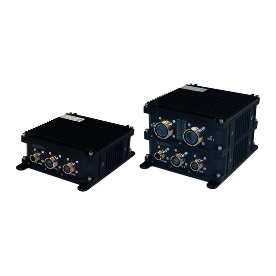
- Page 6 DuraMAR 5915 User Manual List of Figures Figure 1. Standalone Router (MAR-5915-0x) ....................9 Figure 2. Router with Expansion Module (MAR-5915-1x) ................9 Figure 3. Standalone Router Block Diagram ..................... 11 Figure 4. Router with Expansion Module Block Diagram (example) ............12 Figure 5.
-
Page 7: Chapter 1 Introduction
About This Document This manual provides a functional description of the DuraMAR 5915, both as a standalone Cisco 5915 router and with integrated switch modules. Note: This manual is not a comprehensive guide to the Cisco 5915 or IOS. That information is available directly from Cisco Systems at www.cisco.com. -
Page 8: Description Of Safety Symbols
Chapter 1 Introduction DuraMAR 5915 User Manual Description of Safety Symbols The following safety symbols are used in this manual and indicate potentially dangerous situations. Warning! Danger, electrical shock hazard! Personal injury or death could occur. Also damage to the system, connected peripheral devices, or software could occur if the warnings are not followed carefully. -
Page 9: Overview
Cisco’s 5915 Embedded Services Router (ESR) card in an ultra-rugged chassis optimized for harsh military and civil vehicle/aircraft installations. The DuraMAR 5915 is an ideal solution for IP networking technology refresh and situational awareness applications, including those seeking a migration path for legacy Cisco 3200 (3230/3250/3270)-based router subsystems. -
Page 10: Features
Chapter 1 Introduction DuraMAR 5915 User Manual Features Cisco Technology Ruggedized Cisco 5915 Router with Enterprise IOS Software for robust security, management, QoS, VLAN, IPv4/IPv6 routing, IP mobility, interoperability Integrated Services Router (ISR) features support concurrent data, video, and voice services, as... -
Page 11: Functional Description
*** CME-50 Users Base Module The base module of the DuraMAR 5915 contains the Cisco 5915 Router and the Parvus Power Supply (Figure 3). It is available as a standalone router (MAR-5915-0x) or as the bottom module with expansion modules, such as the MAR-5915-1x (Figure 4). -
Page 12: Expansion Modules
Chapter 1 Introduction DuraMAR 5915 User Manual Expansion Modules In expansion module configurations, additional boards are added to the stack, the chassis height is increased, and the EM front panel is customized with unique connectors and LEDs appropriate for the functionality of the boards in that module. -
Page 13: Parvus Power Supply
Features Uses 28V nominal power input voltage (18-33VDC range continuous). DuraMAR 5915-0x power consumption: designed for <15 watts. DuraMAR 5915-1x power consumption: designed for <50 watts. Over-voltage protection ... -
Page 14: Chapter 2 Operating Description
Cable and Connector Identification Starter Cableset for Base Module You should test the DuraMAR 5915 and cabling or interfaces prior to installation in the target system to ensure full operational capability. Full bench-top testing can be performed by using the Parvus starter cableset available for this unit or by using a custom set of cables made specifically for the intended target system, vehicle, or craft. -
Page 15: Base Module Connectors And Leds
DuraMAR 5915 User Manual Chapter 2 Operating Description Base Module Connectors and LEDs Figure 6 shows the connectors and LEDs on the base module front panel. Figure 6. Base Module Connectors and LEDs The table describes the LEDs on the front panel of the base module. -
Page 16: Mounting The System
Chapter 2 Operating Description DuraMAR 5915 User Manual Mounting the System After testing is complete, you can mount the DuraMAR 5915 on the system. Refer to the instructions and dimensions in Chapter 4. Basic Operating Procedures This section describes basic operating procedures, including starting the system console, zeroizing the system, and reloading files after zeroization. -
Page 17: Zeroization
Chapter 2 Operating Description Zeroization For data security, the DuraMAR 5915 provides zeroization capability to erase the application code and configuration data stored in the system. Refer to the Cisco documentation on how to configure the 5915 for zeroization. Once the code is erased, the only method of recovery is to reload code to the system. -
Page 18: Loading Cisco Files
1. Start the Cisco console. 2. Identify the target folder used by the tftp server and place the Cisco IOS software image there. The DuraMAR 5915 ships with a factory default Cisco IOS version of: c5915-entbase-mz.SPA.152-1.GC1.bin 3. Place the configuration file to be reloaded (c5915-entbase-mz.SPA.152-1.GC1.bin or other) in the tftp target folder. -
Page 19: Loading The Ios Configuration After Zeroization
5. After the reload completes, press Enter to display a Router> prompt. The Cisco 5915 IOS configuration has been successfully reloaded. 6. If your DuraMAR 5915 includes expansion modules, you may need to perform additional recovery steps. Refer to "Zeroization Recovery" instructions in each addendum. -
Page 20: Upgrading To A New Ios Image
Chapter 2 Operating Description DuraMAR 5915 User Manual Upgrading to a New IOS Image Use these instructions if you are upgrading the IOS to a new version. Go to the Cisco website www.cisco.com to download the new IOS file. Host PC Setup 1. -
Page 21: Chapter 3 Connector Descriptions
DuraMAR 5915 User Manual Chapter 3 Connector Descriptions Chapter 3 Connector Descriptions This section identifies the pinouts and signal descriptions for the base module. It also provides connector part numbers along with suggested mating connector details. Connector Identification Connector Label... -
Page 22: J2 Ethernet 0 Connector Pinouts
Chapter 3 Connector Descriptions DuraMAR 5915 User Manual J2 Ethernet 0 Connector Pinouts J2 provides the signals for the Ethernet ports in the base module. The standalone router has five Ethernet ports on J2. If the configuration includes any expansion modules, only four ports are available. -
Page 23: 5915-1X Connector Pinout
DuraMAR 5915 User Manual Chapter 3 Connector Descriptions J2 Signal Name Description 38999 Pin # ETH 0_PORT4_RX+ 10/100 RX 4 + ETH 0_PORT4_RX- 10/100 RX 4 - SPARE_11 Populated spare SPARE_12 Populated spare Note: Port 0 TX polarity is opposite of ports 1-4. -
Page 24: J3 Console Connector Pinouts
J3 is the console connector for the Cisco 5915. Connector Alignment: facing the insert side of the connector (pin side). The connector on the DuraMAR 5915 front panel (socket side) is an exact mirror of the picture on the left. P/N: D38999/20FB35SN (Shell Size 11) Figure 10. -
Page 25: Chapter 4 Specifications
Enclosure/Finish: Corrosion Resistant, Aluminum Alloy with Black Anodize Finish per MIL-A- 8625, Type II, Class 2 Dimensions The table summarizes the physical dimensions of the DuraMAR 5915, excluding connectors and mounts. The drawings following the table illustrate the dimensions in different views. Unit... -
Page 26: Standalone Router Dimensions
Chapter 4 Specifications DuraMAR 5915 User Manual Standalone Router Dimensions Figure 11. Standalone Router Angle View Figure 12. Standalone Router Front View Page 26 of 55 MNL-0596-01 Rev A6 ECO-5813 25 Apr 19... -
Page 27: Figure 13. Standalone Router Top View
DuraMAR 5915 User Manual Chapter 4 Specifications Figure 13. Standalone Router Top View MNL-0596-01 Rev A6 ECO-5813 Effective: 25 Apr 19 Page 27 of 55... -
Page 28: Figure 14. Standalone Router Side View
Chapter 4 Specifications DuraMAR 5915 User Manual Figure 14. Standalone Router Side View Page 28 of 55 MNL-0596-01 Rev A6 ECO-5813 25 Apr 19... -
Page 29: Router With Expansion Module Dimensions
DuraMAR 5915 User Manual Chapter 4 Specifications Router with Expansion Module Dimensions Figure 15. Router with EM Angle View MNL-0596-01 Rev A6 ECO-5813 Effective: 25 Apr 19 Page 29 of 55... -
Page 30: Figure 16. Router With Em Front View
Chapter 4 Specifications DuraMAR 5915 User Manual Figure 16. Router with EM Front View Page 30 of 55 MNL-0596-01 Rev A6 ECO-5813 25 Apr 19... -
Page 31: Figure 17. Router With Em Top View
DuraMAR 5915 User Manual Chapter 4 Specifications Figure 17. Router with EM Top View MNL-0596-01 Rev A6 ECO-5813 Effective: 25 Apr 19 Page 31 of 55... -
Page 32: Figure 18. Router With Em Side View
Chapter 4 Specifications DuraMAR 5915 User Manual Figure 18. Router with EM Side View Page 32 of 55 MNL-0596-01 Rev A6 ECO-5813 25 Apr 19... -
Page 33: Mounting Instructions
Chapter 4 Specifications Mounting Instructions You can attach the DuraMAR 5915 to a mounting surface by using the mounting holes on the baseplate or the side. Figure 19 and Figure 20 show the side view of the DuraMAR 5915. Figure 19. Standalone Router Side Boss Figure 20. -
Page 34: 5915 Router Specifications
Chapter 4 Specifications DuraMAR 5915 User Manual 5915 Router Specifications For a complete IOS feature set comparison, refer to the Cisco Feature Navigator at www.cisco.com. Cisco Technology Integrated Cisco 5915 Embedded Services Router (ESR) PCI-104 Card Cisco Enterprise IOS - Base Image or Advanced Services Image ... -
Page 35: Security
DuraMAR 5915 User Manual Chapter 4 Specifications Security Authentication: Route, PAP, CHAP, MS-CHAP Local Password, IP Access Lists, Time-Based Access Control Lists Generic Routing Encapsulation (GRE); Fast Switching, Cisco Express Forwarding, Process Switching, STAC Compression, RTP Header Compression ... -
Page 36: Environmental
Chapter 4 Specifications DuraMAR 5915 User Manual Environmental Qualified to MIL-STD-810G: Operating Temperature: -40° to +71°C (-40° to +160°F) (MIL-STD-810G, Methods 501,502) Storage Temperature: -40° to +85°C (-40° to 185°F) (MIL-STD-810G, Methods 501,502) Operating Shock: 40g, 11ms, 3 pos/neg per axis, 18 terminal peak sawtooth pulses (MIL-STD- 810G, Method 516) ... -
Page 37: Chapter 5 Troubleshooting
DuraMAR 5915 User Manual Chapter 5 Troubleshooting Chapter 5 Troubleshooting Product Identification The product is labeled with the Parvus P/N and serial number. Please refer to this information when communicating with Parvus. Technical Assistance If you have a technical question or if you cannot isolate a problem with your product, please call or e-mail... -
Page 38: Chapter 6 Contact Info
Chapter 6 Contact Info DuraMAR 5915 User Manual Chapter 6 Contact Info Company contact info: Defense Solutions Division Curtiss-Wright 3222 S. Washington St. Salt Lake City, Utah, USA 84115 (801) 483-1533 FAX (801) 483-1523 Website: www.curtisswrightds.com/parvus Sales: +1(800) 483-3152 or (801) 483-1533 slp_sales@curtisswright.com... -
Page 39: Expansion Module
DuraMAR 5915 User Manual Expansion Module Addendum A: Gigabit Ethernet Switches MAR-5915-1x MNL-0596-01 Rev A6 ECO-5813 Effective: 25 Apr 19 Page 39 of 55... -
Page 40: A1 Introduction
DuraMAR 5915 User Manual A1 Introduction The Dual Gigabit Ethernet expansion module for the DuraMAR 5915 contains two Parvus COM-1268 PC/104+ Gigabit Ethernet Switch boards, and is referred to as the COM-1268 EM in this addendum. The COM-1268 EM consolidates switch and router functions into a single hardened subsystem qualified to MIL-STD-810G and MIL-STD-461F environmental conditions, and expands the LAN port count for the DuraMAR 5915 to 19 ports. -
Page 41: Overview
DuraMAR 5915 User Manual A1 Introduction Overview The DuraMAR® 5915 is a rugged Commercial-Off the Shelf (COTS) Cisco IOS-managed mobile router integrated with Cisco’s 5915 Embedded Services Router (ESR) card in an ultra-rugged chassis optimized for harsh military and civil vehicle/aircraft installations. The MAR-5915-1x expansion module features two integrated Gigabit Ethernet switches (COM-1268s) for a total of 19 Ethernet ports, supporting higher port- density application requirements. -
Page 42: Functional Description
Functional Description The two Parvus COM-1268 PC/104+ Gigabit Ethernet switch cards expand the LAN port count for the base DuraMAR 5915 and consolidate switch and router functions into a single hardened subsystem qualified to MIL-STD-810G and MIL-STD-461F environmental conditions. Configurations This addendum applies to the following DuraMAR 5915 configurations. -
Page 43: Internal Ethernet Connections
COM-1268s. For additional information, refer to "Zeroization" on page 46. From the DuraMAR 5915 perspective (front panel, pinouts, cables), the two COM-1268 boards are J4 ETH 1 and J5 ETH2. To the COM-1268 management interface, the two boards are boards 0 and 1 with ports 0/0-1/9. -
Page 44: A2 Operational Description
A2 Operational Description DuraMAR 5915 User Manual A2 Operational Description Cables and Connectors You should test the COM-1268s prior to installation in the target system to ensure full operational capability. Full bench-top testing can be performed by using the Parvus starter cableset available for this unit or by using a custom set of cables made specifically for the intended target system, vehicle, or craft. -
Page 45: Com-1268 Em Connectors And Leds
DuraMAR 5915 User Manual A2 Operational Description COM-1268 EM Connectors and LEDs Figure 26. COM-1268 EM Connectors and LEDs Description SYS1 COM-1268 board 0 Blue light indicates power is on. SYS2 COM-1268 board 1 Blue light indicates power is on. -
Page 46: Basic Operating Procedures
2. Connect the serial DB9 tail to the host PC, and set up a terminal emulator with settings 115200-8-N-1 and no flow control. 3. If the DuraMAR 5915 is not powered on, connect the power cable (CBL-2417-01) or a customer- designed power cable to connector J1 and to a 18-33VDC power source. -
Page 47: A3 Connector Descriptions
D38999/26FF35PN COM-1268 Port Numbers The DuraMAR 5915 and the COM-1268 management interface use different port numbers for the COM- 1268 ports. The table below maps the DuraMAR 5915 signal name to the corresponding COM-1268 board port number, DuraMAR 5915 LED identifier, and COM-1268 configuration port number. For additional information, refer to Figure 24 on page 43. -
Page 48: J4 Ethernet 1 Connector Pinouts
A3 Connector Descriptions DuraMAR 5915 User Manual J4 Ethernet 1 Connector Pinouts J4 provides signals to Parvus COM-1268 Board 0 (Ethernet 1) Serial Management Port (CONS_RXD_RS232) and Ethernet ports ETH-1 0/3-0/9. Connector Alignment: facing the insert side of the connector (pin side). The connector on the front panel (socket side) is an exact mirror of the picture on the left. - Page 49 DuraMAR 5915 User Manual A3 Connector Descriptions J4 Signal Name Description 38999 Pin # ETH 1_P6_A+ 10/100/1000 Port 6 A+ ETH 1_P6_A- 10/100/1000 Port 6 A- ETH 1_P6_B+ 10/100/1000 Port 6 B+ ETH 1_P6_B- 10/100/1000 Port 6 B- ETH 1_P6_C+...
-
Page 50: J5 Ethernet 2 Connector Pinouts
A3 Connector Descriptions DuraMAR 5915 User Manual J5 Ethernet 2 Connector Pinouts J5 provides the signals for COM-1268 Board 1 ports ETH2 1/1, 1/3-1/9. Connector Alignment: facing the insert side of the connector (pin side). The connector on the front panel (socket side) is an exact mirror of the picture on the left. - Page 51 DuraMAR 5915 User Manual A3 Connector Descriptions J5 Signal Name Description 38999 Pin # ETH 2_P5_A- 10/100/1000 Port 5 A- ETH 2_P5_B+ 10/100/1000 Port 5 B+ ETH 2_P5_B- 10/100/1000 Port 5 B- ETH 2_P5_C+ 10/100/1000 Port 5 C+ ETH 2_P5_C-...
-
Page 52: A4 Specifications
A4 Specifications DuraMAR 5915 User Manual A4 Specifications This chapter defines the specifications for the COM-1268 boards used in the MAR-5915-1x. Physical Specifications This section summarizes the physical specifications that are unique to the MAR-5915-1x. For additional information on the MAR-5915-1x chassis, including dimension drawings and mounting instructions, refer to Chapter 4 in the base manual. -
Page 53: Port Features
DuraMAR 5915 User Manual A4 Specifications Port Features Expansion: Any port can serve as a link port for cascading multiple switches, resulting in a blocking architecture. The onboard IrDA (Infrared Data Association) interface supports recognition and management of two stacked COM-1268 boards for management under a common console interface. -
Page 54: Protocol Standards
A4 Specifications DuraMAR 5915 User Manual Protocol Standards IEEE 802.3 10Mbps 10BASE-T (Ethernet) IEEE 802.3U 100BASE-TX 100Mbps (Fast Ethernet) IEEE 802.3AB 1000BASE-T 1000Mbps (Gigabit Ethernet) IEEE 802.1D Spanning Tree Protocol (Bridging) IEEE 802.1P LAN Layer 2 QoS/CoS Protocol for Traffic Prioritization ... - Page 55 DuraMAR 5915 User Manual A4 Specifications {{Parvus back cover, 8.5 x 11 picture inserted in front of text. DO NOT DELETE THE COMMENTS OR THIS PAGE. These comments are only visible in Normal view. The picture hides these comments when you print the manual or view it in Print Layout or Print Preview.}...
Need help?
Do you have a question about the DuraMAR 5915 and is the answer not in the manual?
Questions and answers