Table of Contents
Advertisement
Quick Links
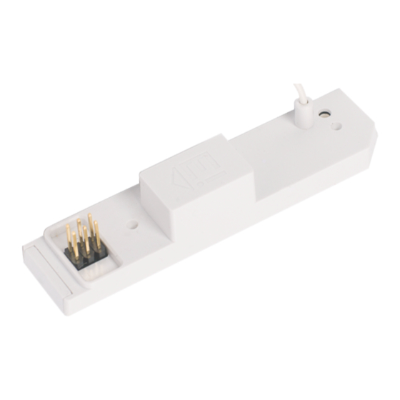
SmartLINK Module Ei3000MRF
for Mains Powered Multi-Sensor Fire / Smoke / Heat /
CO Alarms - Ei3000 Series
Instruction Manual
Read and retain carefully for as long as the product is being used. It
contains vital information on the operation and installation of your
Alarm. The leaflet should be regarded as part of the product.
If you are just installing the unit, the leaflet MUST be given to the
householder. The leaflet is to be given to any subsequent user.
1
Advertisement
Table of Contents

Summary of Contents for EI Ei3000 Series
- Page 1 SmartLINK Module Ei3000MRF for Mains Powered Multi-Sensor Fire / Smoke / Heat / CO Alarms - Ei3000 Series Instruction Manual Read and retain carefully for as long as the product is being used. It contains vital information on the operation and installation of your Alarm.
-
Page 2: Table Of Contents
Contents Installation and House Coding Testing the System Identifying the source of the alarm SmartLINK Troubleshooting Indicator summary table Limitations of Radio Communications Guarantee End of Life (EOL) Check Technical Specifications Contact Us... -
Page 3: Installation And House Coding
1. Installation and House Coding Disconnect the mains power supply. it is now safe to remove the Alarm from its mounting plate. Using a screwdriver, insert into the removal slot on the side of the Alarm (see Removing the Alarm section of the Alarm manual). Push the lower half of the Alarm away from the screwdriver, in the direction of the arrow on the cover (see Fig. - Page 4 Fitting the Ei3000MRF Module To fit the Ei3000MRF Module, first hold the flexible antenna and guide it into its designated hole in the rear of the unit until about 2/3 of its length is inserted (Fig. 2a). Then, hold the module housing (Fig. 2b) and plug it into the Alarm, being careful to align the pins and keeping them perpendicular to the base as the...
- Page 5 Alignment Alignment Figure 2b Figure 2c Note: If the Alarm starts beeping rapidly after the module has been fitted, the module has to be reset (see Factory Reset section).
- Page 6 The LED on the side of the Alarm may flash red, blue, green. Re-attach the Alarm to the mounting plate. Switch back on the mains power. Check for the green LED on the Alarm cover. Power supply to the Ei3000MRF will be confirmed by the LED on the side of the Alarm flashing in red, blue and green (see Fig.
- Page 7 House Coding the Unit Using a screwdriver, press and hold the House Code button on the side of the unit until the LED lights up blue (see Fig 4). Immediately release the button, the LED will flash blue rapidly and then stop. Figure 4 Note: If the LED light up in a different colour than the one you expected, keep the house code button pressed until the colour you are looking for...
- Page 8 The flashing will repeat every 5 seconds thereafter. Repeat this procedure for all Alarms in the system. Note: If the LED flashes red rapidly after the House Code button is released, the communication has failed between the Alarm and the module.
- Page 9 N.B. We recommend, for ease of installation and RF communication, that up to 12 RF devices can be installed in any one RF coded system. Please contact us for further advise if additional RF devices are required. You can exit this mode by pressing the House Code button on one of the RF Alarms.
- Page 10 Remote House Coding If you want to add an Alarm in a system that has already been house coded, follow these steps: Using a screwdriver, press and hold the House Code button of one of Alarms in the system until you see all colours flashing - red, blue, green (typically takes about 8 seconds) and then release.
- Page 11 Factory Reset Sometimes in order to resolve an RF communication issue it may be necessary to reset (factory reset) and House Code the system again. To do so, press and hold the House Code button until you see a flashing blue light (approx.
- Page 12 Alignment Alignment Figure 5a Figure 5b Figure 5c...
- Page 13 Mixed Hardwired Interconnect and Wireless Interconnect (Hybrid) System If the interconnected system includes a mix of CO and Fire detection, it is important to know that the hardwire interconnect line does not communicate the alarm type (Fire or CO), whereas the RF interconnection does.
-
Page 14: Testing The System
2. Testing the System Frequent testing of the system is a requirement to ensure its continued and safe operation. Guidelines and best practices for testing are as follows: 1. After the system is installed. 2. Regularly (monthly testing is recommended). 3. -
Page 15: Identifying The Source Of The Alarm
This will take between 20 to 45 seconds depending on the number of Alarms and their locations in the system, e.g. a system with 12 Alarms may take up to 45 seconds for all to sound. Release the test button when the test is completed. -
Page 16: Smartlink Troubleshooting
The Alarm with the red LED flashing is the source of the alarm. We recommend however, that an Ei450 Alarm Controller is used. As during an alarm, an icon on the Ei450 will indicate if it is a CO or Fire incident allowing you to act rapidly. - Page 17 (ii) rotate / re-locate the Alarms (e.g. move them away from metal surfaces or wiring). After making these changes to the RF signal path, the SmartLINK signals may still not be reaching all the Alarms in your system, even though they have already been House Coded successfully (see Section on “Limitations of Radio Communications”).
-
Page 18: Indicator Summary Table
5. Indicator summary table Sound What it means Blue Green Module Power up when fitting RF module into the Alarm and/or when fitting the Alarm onto the mounting plate RF transmission when entering/exting House code mode 1 x 3.5sec Normal RF transmision for communication between devices RF transmission when entering/exting Monitoring mode (contact us for more details) -
Page 19: Limitations Of Radio Communications
6. Limitations of Radio Communications Ei Electronics radio communication systems are very reliable and are tested to high standards. However, due to their low transmitting power and limited range (required by regulatory bodies) there are some limitations to be considered: (i) Receivers may be blocked by radio signals occurring on or near their operating frequencies, regardless of the House Coding. -
Page 20: Guarantee
This guarantee excludes incidental and consequential damage. If this RF SmartLINK Module should become defective within the guarantee period, it must be returned to Ei Electronics, with proof of purchase, carefully packaged and with the problem clearly stated. We shall at our discretion repair or replace the faulty unit. -
Page 21: End Of Life (Eol) Check
8. End of Life (EOL) Check Check the ‘replace by date’ label on the Ei3000MRF modules. If the date has been exceeded then the module should be replaced. The most convenient time to check is when the Alarm signals by 3 short Block E1 chirps with 3 yellow LED flashes every 48 seconds that it has reached its end of useful life and needs to be changed. -
Page 22: Technical Specifications
9. Technical Specifications Power Supply: Powered by Alarm head unit RF Range: A minimum of 100 metres in free space RF Visual Indicator: 3 colour LED: Blue, Red, Green Flashing Blue: RF transmission Red, Blue, Green: Power up sequence and remote house code mode entry RF Frequency: 868.499MHz (1% duty cycle) -
Page 23: Contact Us
12 RF devices can be installed in any one RF coded system. Please contact us for further advice if additional RF devices are required. Hereby, Ei Electronics declares that this Ei3000MRF SmartLINK Module is in compliance with the essential requirements 0889 and other relevant provisions of Directive 2014/53/EU. - Page 24 Aico Ltd Maesbury Rd, Oswestry, Shropshire SY10 8NR, U.K. Tel: 01691 664100 www.aico.co.uk Ei Electronics Shannon, V14 H020, Co. Clare, Ireland. Tel:+353 (0)61 471277 www.eielectronics.com P/N B19047 Rev4 © Ei Electronics 2022...
Need help?
Do you have a question about the Ei3000 Series and is the answer not in the manual?
Questions and answers