Table of Contents
Advertisement
Advertisement
Table of Contents

Subscribe to Our Youtube Channel
Summary of Contents for ATMOX ACE 2.0
- Page 1 Moisture Control & Heat Reduction...
- Page 2 All specifications and designs are subject to change without notice. This installation guide and its contents are owned by ATMOX INC and are protected under the US Copyright Act and other intellectual property laws. All trademarks, service marks, logos and the like (whether registered or unregistered) are owned and controlled by ATMOX INC.
-
Page 3: Table Of Contents
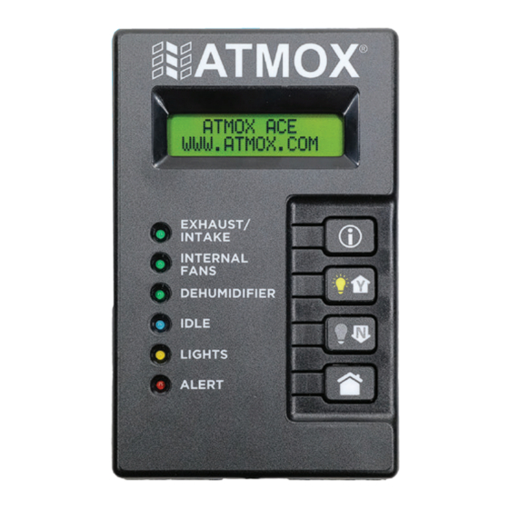
TABLE OF CONTENTS OPERATING PRINCIPLE ......4 OVERVIEW ..........17 INFORMATIONAL SCREENS ....4 WIRING EXPLANATION ......18 NOTIFICATIONS ........5 PRIMARY LOW VOLTAGE WIRE ... 18 NAVIGATION & SETTINGS ...... 7 SUPPLEMENTAL LOW VOLTAGE LOW VOLTAGE OPERATOR’S GUIDE MAINTENANCE ......... 7 WIRE ............ -
Page 4: Operating Principle
OPERATING PRINCIPLE Unfinished spaces of your house need proper ventilation and/or dehumidification. The goal of ATMOX is simple – reduce the moisture level in your crawl space and reduce both heat and moisture levels in your attic. The basic principle of how it works is also simple. Ventilate with “good” air from the outside only when it will improve conditions in the space. -
Page 5: Notifications
OPERATOR’S GUIDE The ATMOX system uses a series of calculations based on the data to determine the best action. Temperature determines: • If attic fans should operate for high heat. (APEX) • If the outside temperature is within parameters to allow ventilation and to avoid air that is too cold or too hot. - Page 6 ALERT ALERT When the Alert light is solid red, the alerts are a notification of a hardware issue with the ATMOX system. These errors will limit or cease operation and should be addressed immediately. For any system alerts, contact your installer for assistance or view more CAUTION detailed information in TROUBLESHOOTING section.
-
Page 7: Navigation & Settings
System Alerts If the ATMOX system is showing an alert, then the system may not be operating or may be notifying you of another potential issue. Please check periodically to make sure that the display has no alerts needing attention. -
Page 8: Frequently Asked Questions
OPERATOR’S GUIDE Water Management (ACE) It is important to note that the ATMOX system is a moisture management system and not a water management system. Dry air or a dehumidifier cannot get rid of standing water in a crawl space. -
Page 9: Safety Instructions
(2) this device must accept any interference, including interference that may cause undesired operation of the device. The ATMOX Controller 2.0 conforms to unified standard UL 60730-1 and UL 60730-2-9 and CSA standard E60730-1 and CSA standard E60730-2-9. -
Page 10: Specifications
2. Sync Cable 3. Quick Splice Connectors 4. Installation Guide General tools and supplies needed for installation are not included. Screws for mounting controller, sensors or other ATMOX components should be selected based on the surface to which you are mounting. -
Page 11: Placement & Configuration Ace
PLANNING PLACEMENT & CONFIGURATION - ACE Before beginning installation, take a moment to review components that you will be installing. As you review steps, think about where components will be placed. A little pre-planning will make things go very smoothly when installing. Controller and Sensor Placement Display... -
Page 12: Placement & Configuration Apex
PLANNING PLACEMENT & CONFIGURATION - APEX Controller and Sensor Placement Display Controller Inside Sensor Outside Sensor ATTIC FUNCTION BY OUTPUT Lights turn on Constant Power when manually activated. Fans run when the outside air is beneficial. -
Page 13: Low Voltage Wiring Planning
PLANNING LOW VOLTAGE WIRING PLANNING Determine where components will be placed. The controller location will dictate the origin of your wiring. It is important to understand the function of each component in the space. The function (not necessarily the type of component) determines which output line the component will be wired to. These functions should be determined prior to running low voltage wire to components. -
Page 14: Fans
The use of fans or lights not manufactured by ATMOX may not be compatible with the ATMOX controller and may cause an electrical surge or damage the controller. Damage caused by noncompatible components or incorrect wiring is not covered under the ATMOX product warranty. -
Page 15: Controller Installation
CONTROLLER & SENSORS CONTROLLER INSTALLATION DO NOT PLUG CONTROLLER INTO ELECTRICAL OUTLET AT THIS TIME. Mount using four screw holes by an electrical outlet in or near the attic/ crawl space. Don’t place controller in an outside location. In attic, don’t place within two feet of CAUTION the roof rafters. -
Page 16: Wood Moisture Sensor
CONTROLLER & SENSORS WOOD MOISTURE SENSOR Use two screws to mount on a joist or beam inside attic/crawl space. Plug jack into WOOD MOISTURE port. It may take a few days for the wood sensor to acclimate and provide accurate readings. -
Page 17: Overview
LOW VOLTAGE WIRING OVERVIEW ATMOX components such as fans and lights are designed for connection to controllers via low voltage wiring. Use 14/2 low voltage wire. This wire can have different grooves or writing. Pick one side as positive and the other as negative. Be consistent throughout installation. -
Page 18: Wiring Explanation
LOW VOLTAGE WIRING WIRING EXPLANATION FOR EACH OUTPUT Primary Low Voltage Wire Negative (grooved side) Black Terminal Block Colored Terminal Block Positive (smooth side) Quick Splice Connectors Connector Supplemental Wire Low Voltage Wire Fan or Accessory PRIMARY LOW VOLTAGE WIRE Push exposed copper up and under one side Split wire about two inches from end. -
Page 19: Supplemental Low Voltage Wire
LOW VOLTAGE WIRING SUPPLEMENTAL LOW VOLTAGE WIRE On primary wire, select location where Take the end of the POSITIVE side of the supplemental wire will be attached. Split wire. supplemental wire. Insert the end of the wire into the connector until it hits the plastic stop. Pull apart the two sides to make a loop of about three inches. -
Page 20: Connector Wires
LOW VOLTAGE WIRING FASTENING WIRE & ATTACHING CONNECTOR WIRES Secure wire to joists. Take the end of the POSITIVE side of the connector wire (black wire). Insert the end of the Create a drop loop location where you want to connector wire into the connector until it hits the attach the component. - Page 21 LOW VOLTAGE WIRING RESETTING QUICK SPLICE CONNECTORS Follow these steps only if a connector needs to be redone. Open cover and wedge connector open. Pull apart and remove wires. 3A – If needed, reinsert the metal piece. 3B – If needed, push the metal piece up. REUSING CONNECTOR WIRES Follow these steps only if a metal tip is missing or damaged.
-
Page 22: Display Connection
SETUP DISPLAY CONNECTION To setup the controller, you will use the display. It is easiest to make a temporary connection near the controller and then move to permanent viewable location within the house once setup is complete. (See page 25.) Plug jack from extension cable into the bottom of the display. -
Page 23: Setup Screens
SETUP APEX CONTROLLER ACE CONTROLLER SETUP SCREENS SETUP SCREENS SETUP MENU SETUP MENU BEGIN PRESS i BEGIN PRESS i WOOD SENSOR STANDARD ATTACHED Y SETUP Y Note: For non-standard setup, see detailed SNOW MODE information on setup selection in the SETTINGS ENABLE N section. -
Page 24: Power Booster Sync
SETUP POWER BOOSTER SYNC The following instructions are to setup and sync a Power Booster AFTER the initial setup of the controller and display. Depending on output use and wiring, it is possible to have alerts related to voltage not being detected. This will clear out after syncing. -
Page 25: Display Installation
SETUP DISPLAY INSTALLATION Once all of the set up and testing is complete, place display in a location that is easily viewable such as a garage or closet. You do not need a power source here, but you will need to connect to controller with an extension cable. -
Page 26: Settings Menu
SETTINGS MENU SETTINGS MENU Press and hold the home button for five seconds to access the menu to make changes to settings, for testing, for manual operation, and for resetting controller. Once in the menu, press (i) to scroll forward and to save changes to settings or to execute a change. Settings can be changed by using the (Y) and (N) buttons to indicate Yes or No answers or as Up and Down arrows to change values. - Page 27 SETTINGS MENU The set point determines how long the forced FV DURATION MINUTES 30M ventilation will occur. The set point determines the minimum temperature FV MINIMUM TEMP INSIDE 40°F inside the crawl space to allow the forced ventilation. Set to (Y) to turn the relative humidity alert on. INSIDE RH ALERT N This set point indicates when the average relative...
- Page 28 SETTINGS MENU Set to (Y) or (N) depending on whether lights on LIGHTS OPERATE Y GREEN output are being installed. Change to (N) to remove any alert from Missing OUTPUT DETECTION ALERTS Y Output Detection. If the controller detects any type of issue with OUTPUT ERROR RESET N wiring on an output, it will shut that output off as a...
- Page 29 SETTINGS MENU During setup, testing begins automatically and will GREEN OUTPUT TEST 15 MIN N check for errors even if output not selected. In this settings menu, you must change to (Y) and press (i) to begin testing. Go physically check that all lights on this output are running properly.
-
Page 30: Apex Settings
SETTINGS MENU APEX SETTINGS Press (i) to begin and keep scrolling through to next SETTINGS/TESTING SCROLL: PRESS i setting. Software version of display and controller. APEX 03.XX.XX APEX 01.XX.XX Set to (Y) or (N) depending on whether wood moisture WOOD SENSOR ATTACHED Y sensor is being installed. - Page 31 SETTINGS MENU During setup, testing begins automatically. In this RED OUTPUT TEST 15 MIN N settings menu, you must change to (Y) and press (i) to begin testing. Go physically check that all attic fans on this output are running properly. Testing will time out automatically after 15 minutes.
-
Page 32: Checklist
This checklist is a summary of the main items that should be checked off as part of the installation completion or when conducting an inspection. This list is not inclusive of related work that may be performed in conjunction with an ATMOX system installation. Add a check mark to the first column if task completed. - Page 33 INSTALLATION CHECKLIST CHECK SECTION INSTALLATION STEP PAGE MARK COMPONENTS Components such as fans, dehumidifiers and lights installed. 11-12 All wired to correct colored output according to function. Wiring fastened to be out of the way. Any accessory components such as vent covers installed, and space properly secured.
-
Page 34: Setup Error Messages
TROUBLESHOOTING ERROR MESSAGES DURING SETUP During setup, the system is checking for components installed on each output line regardless of whether or not selected. If components are not properly installed prior to setup, any of the following error messages may appear. If any error message is active (not cleared or skipped) for more than 30 minutes, the setup will timeout and start over. -
Page 35: Alerts
TROUBLESHOOTING ALERTS ALERT EXPLANATION Wood moisture sensor is reading an elevated moisture level. If this alert WOOD MOISTURE remains active for a period of time, the space should be checked. ALERT Water alert sensor has detected water at the location of the sensor. If HIGH WATER this alert is triggered, the space should be checked immediately for a ALERT... -
Page 36: Software & Hardware Compatibility Errors
ACE and APEX components. SOFTWARE NOT COMPATIBLE The display and controller are Contact ATMOX for more information on component and running incompatible software software compatibility to determine next step. versions. This could happen if using equipment from different manufacturing periods. -
Page 37: Hard Reset
TROUBLESHOOTING INSTRUCTIONS FOR A HARD RESET On the controller or power booster, there is a small pin hole in the upper left side of the front. While the controller or booster is plugged in, insert a small paper clip in the hole and hold for a few seconds until the indicator light is a solid green. - Page 38 TROUBLESHOOTING ALERT/ISSUE SOLUTION POSSIBLE CAUSE COMM ERROR BOOSTER 1 Issue with data sync between The controller is not properly communicating with the power controller and power booster. booster. • Check the indicator light on the power booster. If it is solid, then it is not configured and must be synced to the controller.
- Page 39 TROUBLESHOOTING ALERT/ISSUE SOLUTION POSSIBLE CAUSE Wood moisture sensor installed but screen not showing. Settings are not aligned with If wood sensor is being installed, setting needs to indicate components installed. this by selecting (Y) under screen for WOOD SENSOR – ATTACHED Y.
-
Page 40: Component Wiring Errors
TROUBLESHOOTING COMPONENT WIRING ERRORS For all errors listed below, first determine the cause and follow steps for solution in the table. Then to clear error and return to operation you must: 1. Once components corrected, reset the output line. This is done in the settings menu on screen OUTPUT ERROR –... - Page 41 TROUBLESHOOTING ALERT/ISSUE POSSIBLE CAUSE SOLUTION YELLOW ERROR ORANGE ERROR GREEN ERROR RED ERROR VOLTAGE ISSUE VOLTAGE ISSUE VOLTAGE ISSUE VOLTAGE ISSUE VOLTAGE ISSUE VOLTAGE ISSUE VOLTAGE ISSUE VOLTAGE ISSUE RED BOOSTER ORANGE BOOSTER YELLOW BOOSTER GREEN BOOSTER Components on one output line Check the installed components on output line with issue to see if exceed maximum watts.
-
Page 42: Testing Issues
TROUBLESHOOTING TESTING ISSUES The following issues are related to component operation during testing. If there is any type of alert, address that issue first to clear errors. POSSIBLE CAUSE SOLUTION All components on the output line are not running. The polarity of the primary low Temporarily switch the low voltage wire to the colored and black voltage wire is reversed. - Page 43 3-year warranty period. ATMOX products are designed to improve conditions in the crawl space, basement or attic, yet are limited by atmospheric and natural conditions over which ATMOX has no control and which are not covered by this warranty.
- Page 44 ATMOX INC 10612-D Providence Road #229 Charlotte, NC 28277 Phone: 704-248-2858 Fax: 704-675-9858 Email: info@atmox.com Website: www.atmox.com...
Need help?
Do you have a question about the ACE 2.0 and is the answer not in the manual?
Questions and answers
How do I turn on the fans manually
To manually turn on the fans for the ATMOX ACE 2.0, change the AUTO setting to (Y) to force the operation of the fans for 12 hours. This will override automatic operation, and an hourly countdown will appear on the main informational screens. To stop or change this during the countdown, return to this setting.
This answer is automatically generated