Table of Contents
Advertisement
Quick Links
Operating Instructions
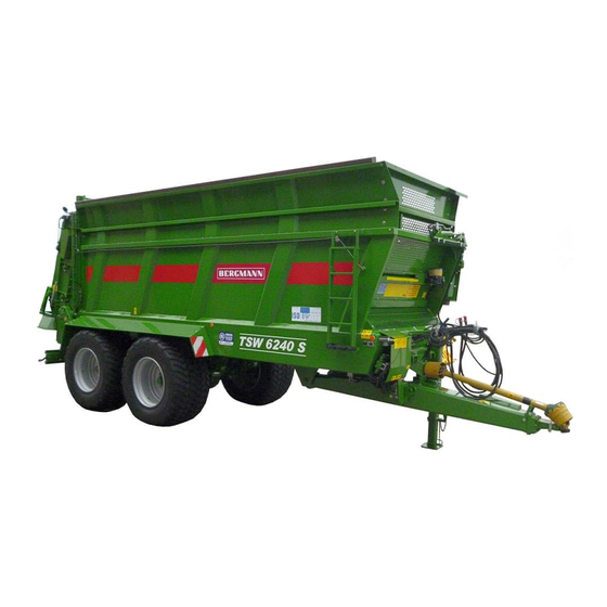
Universal and Industrial Spreader
TSW 4190 S
TSW 5210 S
TSW 6230 S
TSW 6240 S
Quality "Made in Goldenstedt"
Ludwig Bergmann GmbH
Maschinenfabrik
Hauptstraße 64 – 66
49424 Goldenstedt / Germany
Tel.: +49 (0) 44 44 - 20 08 -0
Fax: +49 (0) 44 44 - 20 08 88
info@l-bergmann.de
www.bergmann-goldenstedt.de
M 4190 SZ
M 5210 SY
M 6230 SY
M 6240 SY
Customer Service:
Tel.: +49 (0) 44 44 - 20 08 15
Fax: +49 (0) 44 44 - 20 08 43
kundendienst@l-bergmann.de
Spare Parts Stock
Tel.: +49 (0) 44 44 - 20 08 16
Fax: +49 (0) 44 44 - 20 08 25
ersatzteillager@l-bergmann.de
4190: 1-135 - 1-270
5210: 1-135 - 1-284
6240: 1-135 - 1-286
Art. no.: 011005GB0209
As of:
02.2009
Modify:
12.2013
Advertisement
Table of Contents

Subscribe to Our Youtube Channel
Summary of Contents for bergmann TSW 4190 S
- Page 1 Operating Instructions Universal and Industrial Spreader TSW 4190 S M 4190 SZ TSW 5210 S M 5210 SY TSW 6230 S M 6230 SY TSW 6240 S M 6240 SY 4190: 1-135 - 1-270 5210: 1-135 - 1-284 6240: 1-135 - 1-286 Art.
-
Page 2: Notices For The User
Modifications that are not in accordance with or allowed by these operating instructions may only be carried out with written permission from Bergmann. Due to the fact that our products and technical standards are constantly being developed, these operating instructions are subject to change without notice. -
Page 3: Table Of Contents
Notices for the User Table of Contents Notices for the User ....................2 Vehicle Data ............................2 Preface ..............................2 Instructions for work safety ..............................2 Table of Contents ..........................3 Dear customer, ............................ 5 Product Liability, Obligation to Inform ....................5 Product Transfer Instructions ...................... - Page 4 Notices for the User Handling the Electromagnetic Remote Control........................43 Adjusting the Rotary Potentiometer with Comfort Controls ....................44 Important Notices for Electro-Magnetic Remote Control ..............45 Follow-up Axle (optional) .........................45 Forced Steering (optional) ........................46 Safety Notice ..................................46 Adapting the Tractor to the Trailer ............................47 Coupling the Universal Spreader: ............................
-
Page 5: Dear Customer
In order to prove that the vehicle and the operating instructions were transferred properly, written confirmation is needed. You will find a transfer statement below which must be filled out and returned to Bergmann after transfer. According to the German product liability law, every farmer is the owner of a business. - Page 6 Notices for the User As of: 02/2009...
-
Page 7: Product Transfer Instructions
Information about optional and extra equipment was provided. Informed that reading the operating instructions is absolutely necessary In order to prove that the vehicle and operating instructions were transferred properly, the transfer statement must be filled out, signed and returned to Bergmann. Ludwig Bergmann GmbH Maschinenfabrik D –... -
Page 8: General Information
Notices for the User General Information Read the operating instructions thoroughly and observe safety notices before initial start-up! In the case that something is still unclear, please contact the responsible Bergmann sales representative or our customer service department (Tel. 49-4444/2008-15). Intended Use The universal spreader is designed exclusively for the standard operation of spreading manure and compost (intended use). -
Page 9: Identification Plate
The identification plate is located on the front right side of the frame. . The vehicle ident. No. (VIN) is embossed in the frame near this plate. Queries and/or guarantee claims cannot be processed without this number. Manufacturer Ludwig Bergmann GmbH Maschinenfabrik Hauptstr. 64 - 66 D-49424 Goldenstedt... -
Page 10: Technical Data
Notices for the User Technical Data M6230SY TSW6230S M4190SZ TSW4190S M5210SY TSW5210S M6240SY TSW6240S Weights Gross vehicle weight With high drawbar 16,000 16,000 16,000 16,000 22,000 22,000 With low drawbar (ball coupl.) 18,000 18,000 18,000 18,000 24,000 24,000 Gross axle weight 14,000 14,000 20,000... -
Page 11: Safety Notice
Notices for the User Safety Notice The warning symbols are provided for the safety of all persons who work with the universal and industrial spreader. The notices identify vehicle specific characteristics which need to be observed in order to provide for flawless vehicle operation. The warning symbols are shown and explained below. ... - Page 12 Notices for the User B06-0542 B06-0548 Be careful of moving parts! Never Be careful of high-pressure liquid reach into the running machine! Do leaks. Observe notice in technical open remove safety handbook! equipment while motor is running! B06-0543 B06-0549 Only touch machine parts when they come to a complete standstill! Switch off motor and remove Before working on spreader disks,...
- Page 13 Notices for the User B06-0609 B06-0719 Never reach into areas where Check the scraper floor setting hands can be crushed as long as regularly and correct if necessary! parts are moving! B06-0666 B06-0738 Do not reach between tractor and Check the beater drive chain the coupling equipment during tensioning system regularly and coupling operations!
-
Page 14: General Safety And Accident Prevention Regulations
Notices for the User B06-0870 Konstantstrom - System The height can exceed 4000 mm Drehknopf bis Anschlag when dosing wall is extended. Be ausdrehen careful of overhead lines and driving through bridges. Konstantdruck - System Load Sensing - System (LS) Drehknopf bis Anschlag eindrehen B06-0870... -
Page 15: Driving
Notices for the User Driving Couple the trailer and equipment properly. Handling, steering and braking ability are influenced by attachments, trailers and ballast weight. Therefore, ensure there is sufficient steering and braking ability! Observe allowable axle loads and total weight! ... -
Page 16: Pto Shaft Operation
Notices for the User PTO Shaft Operation Mount and dismount the PTO Never engage the PTO shaft when the motor shaft only when the motor is off is off! and the ignition key has been removed! After power been switched off the unit can continue to... -
Page 17: Brakes And Tires
Notices for the User Brakes and Tires Check the brakes prior to every use! A thorough brake system inspection is to be conducted on a regular basis! Adjustments and repairs to the brake system may only be conducted by a qualified workshop or an authorized brake service! ... -
Page 18: Important Information For Vehicle Operation
Notices for the User Important Information for Vehicle Operation The length of the PTO shaft must be adapted to the tractor being used! Observe the maintenance installation instructions regarding Walterscheid shaft. Max 1000 rpm Raise the jack stand and lock it in place prior to operation! ... -
Page 19: Initial Start-Up And Functions
Initial Start-up and Function Initial Start-up and Functions Mode of Operation The material in the cargo area is moved to the spreader unit by the scraper floor. The dosing wall makes fine spreading of free-flowing and semi-free-flowing materials. The spreading / milling beaters in the rear mill and spread the material. -
Page 20: Coupling To The Tractor
Initial Start-up and Function Coupling to the Tractor When coupling and uncoupling the universal spreader with the tractor there is danger of injury! For this reason never stand between or the universal spreader and the tractor or behind the trailer during coupling operations if the trailer is not secured against rolling with the parking brake or wheel chocks. -
Page 21: Parking Equipment
Initial Start-up and Function Parking Equipment Mechanical Jack Stand The universal spreader is standard equipped with a mechanical jack stand. The vehicle may only be placed on the jack stand when not loaded. The parking area must not exceed a maximum incline of 7°. The vehicle is to be secured with the parking brake and wheel chocks when using the jack stand. -
Page 22: Mechanical Support Jack
Initial Start-up and Function Mechanical Support Jack The uncoupled vehicle is supported by the mechanical support jack. For coupling and uncoupling the height of the vehicle is adjusted to the coupling height of the tractor. This jack stand can be used when the vehicle is loaded or empty. - Page 23 Initial Start-up and Function Malfunctions Malfunction Cause Solution Connecting shaft too long Shorten connecting shaft Support device can not be Spindle or gearbox defective extended Repair support device Support tube or inner tube bowed Support device can only be Use load force before contact Wrong force setting extended to ground with ground...
- Page 24 Initial Start-up and Function Uncoupling: At the end of crank rotation, turn crank back slightly. Danger of crank kickback Park the vehicle on firm, level surface, if necessary place a suitable block under the support device. Secure the vehicle against rolling (parking brake, wheel chocks). ...
-
Page 25: Hydraulic Jack Stand (Optional)
Initial Start-up and Function Hydraulic Jack Stand (optional) A hydraulic jack stand can be mounted to the universal spreader as a special option. It is operated by a double action control unit on the tractor. Coupling the Universal Spreader: Set coupling on the tractor so that there sufficient space for PTO shaft. ... -
Page 26: Pto Shaft
Initial Start-up and Function PTO shaft Only couple the PTO shaft when the motor is off, the PTO shaft is disengaged and the ignition key has been removed Never engage the PTO shaft when the motor is off! ... - Page 27 Initial Start-up and Function Using the Quick Coupling Coupling: The black plastic ring (a) is pushed back and locked into place. Slide the mounting yoke over the coupling shaft. Push the yoke until the catch (a) locks into place (The locking is clearly audible and the black plastic ring slips forward).
-
Page 28: Body
Extension Walls (optional) If desired, the side walls can be extended to different heights using different attachment, depending on the vehicle type: M 4190 SZ / TSW 4190 S: 250 mm (straight) M 5210 SY / TSW 5210 S /... - Page 29 Initial Start-up and Function To assemble wall extensions with a height of 250 mm 300 mm or 450 mm proceed as follows: 1. Remove the plastic scraper rails from the side walls as well as the protective screen from the front wall.
-
Page 30: Scraper Floor
Initial Start-up and Function Scraper Floor The scraper floor consists of four chain strands with transport bars made of U-steel screwed between them. This design ensures the load is transported safely to the spreader unit. The scraper floor is driven by the tractor’s hydraulic system. The hydraulic oil flow is fed under controlled volume into an oil motor which transfers its rotational movement by way of a gearbox to the feed drive shaft on the rear of the vehicle. -
Page 31: Dosing Wall
Initial Start-up and Function Dosing Wall The dosing wall height can be adjusted by way of two hydraulic cylinders. This can be carried out directly from the control unit in the tractor or an electrical control unit (option). When spreading free-flowing semi-free-flowing materials the dosing wall height adjustment is used in... -
Page 32: Spreader Unit
Initial Start-up and Function Spreader Unit The universal spreader can be equipped with different spreader units for spreading materials. Design Vehicle Type TSW Disk spreader system 2 spreader disks (1,000 mm diameter, 8 mm thick), each plate with 6 adjustable spreader blades (8 mm thick), (only in conjunction with two- or three-beater spreader). -
Page 33: Design Vehicle Type M
Initial Start-up and Function Design Vehicle Type M Four beater spreader unit With four vertical beaters, Type SZ: 1,400mm throughput with bolted double tines, direct beater drive by way of chainless drive train consisting of a main gearbox and four beater gearboxes Vehicle type: 4190 Type SY:... -
Page 34: Lubrication Systems
Initial Start-up and Function Lubrication systems Automatic Lubrication System for the Milling Unit Drive Chains (optional) An automatic lubrication system for the milling unit drive chains is available on request (vehicle type TSW). When the scraper floor is in operation, the milling unit roller chains are automatically lubricated by a brush. - Page 35 Initial Start-up and Function Malfunctions Malfunction Cause Solution Pump is not turning No power supply to pilot box Repair electrical system in tractor or spreader Pump defective Call customer service Pump turns in the wrong Electrical socket installed Install socket properly direction (must turn counter- improperly clockwise)
-
Page 36: Hydraulic System
Initial Start-up and Function Hydraulic system The standard universal spreader is controlled by a control unit in the tractor. After coupling the hydraulic lines to the tractor, the desired function can be carried out using the control unit in the tractor. -
Page 37: Ls Connection (Optional)
Initial Start-up and Function LS Connection (optional) For tractors with load-sensing systems, knob 1 must be closed to the stop on the control block and the LS line must be connected to the tractor. B06-0862 Image: knob When driving on public roads, the control unit of the tractor must be disconnected from the pressure! Hydraulic feed drive with manual control For hydraulic feed drive with manual control all functions are controlled by way of the control unit in... -
Page 38: Installation Of The Flow Regulator With Knob
Initial Start-up and Function Installation of the Flow Regulator with Knob It is forbidden to mount the flow regulator in the tractor cab. Mounting hydraulic lines in the tractor cab is not allowed. The flow regulator is mounted at the front end of the hydraulic arm on the drawbar as shown in the picture. -
Page 39: Pilot Box (Optional)
Initial Start-up and Function Pilot box (optional) The pilot box is available on request. With the pilot box a circulation hydraulic system is required. This means that while material is being spread hydraulic oil must constantly be circulated into the spreader and back into the tractor In this case a pressure hose will be connected to the tractor’s supply line and the return line will be connected to the free return on the tractor. -
Page 40: Adjusting The Rotary Potentiometer In The Pilot Box
Initial Start-up and Function Adjusting the Rotary Potentiometer in the Pilot box Depending on the tractor, it may be necessary to adjust the scraper floor speed. The rotary potentiometer 4 (image Pilot box) functions are as follows: Position 0 Scraper floor off Position 0.5 Scraper floor moves very slowly Position 10... -
Page 41: Comfort Control (Optional)
Initial Start-up and Function Comfort Control (optional) The comfort controls are available on request. The hydraulic system is a circulation hydraulic system. This means that while material is being spread hydraulic oil must constantly be circulated into the spreader and back into the tractor For this a pressure hose will be connected to the tractor’s supply line and the return line will be connected to the free return on the tractor. - Page 42 Initial Start-up and Function 1. Main switch: ON – OFF 0 – Control unit on I – Control unit off 2. Indicator light: lights when power supply is switched on. 3. Knob: Scraper floor speed (if equipped with UNI CONTROL S, no function 4.
-
Page 43: Handling The Electromagnetic Remote Control
Initial Start-up and Function Manual scraper floor speed control (without UNI CONTROL S). CONTROL UNI Speed regulated control of the scraper floor speed using additional computer UNI CONTROL S from Müller- Elektronik (special feature). For computer operation, please see the operating instructions supplied by Müller- Elektronik. -
Page 44: Adjusting The Rotary Potentiometer With Comfort Controls
Initial Start-up and Function Adjusting the Rotary Potentiometer with Comfort Controls Depending on the tractor, it may be necessary to adjust the scraper floor speed setting. The rotary potentiometer should function as follows: Position 0 Scraper floor off Position 1 Scraper floor moves very slowly ... -
Page 45: Important Notices For Electro-Magnetic Remote Control
Initial Start-up and Function Important Notices for Electro-Magnetic Remote Control During long breaks in hydraulic system operation e.g. when driving from the field to the loading area the hydraulic system pressure should be switched off or the main switch for the electromagnetic controls should be switched off. -
Page 46: Forced Steering (Optional)
Initial Start-up and Function Forced Steering (optional) If desired, the steering axles can be used as forced axles. In practical use a forced steering axle provides for more driving safety, because it absorb transverse forces (such as when cornering) as opposed to a follow-up axle. -
Page 47: Adapting The Tractor To The Trailer
Initial Start-up and Function Adapting the Tractor to the Trailer To establish the connection to the tractor coupling points are needed on the tractor, which adhere to the standard proposed by the VDMA Special Interest Group Agricultural Machinery (Image: Image of the master cylinder). -
Page 48: Adjusting The Steering
Initial Start-up and Function Adjusting the Steering The setting of the steering axle is to be tested after coupling and daily before operation and corrected if necessary. This is carried out as follows: Park the tractor on a flat, level surface after moving straight forwards. Turn the ball valves as shown in Image: Settings 1.-3. -
Page 49: Uncoupling
Initial Start-up and Function Driving with follow-up steering axle (Image: Settings 1.-3. Axle pos. 2.1. With follow-up steering shown in valves remain open (Image: Settings 1.-3. Axle pos. 2.1). The wheels of the steering axle and are free and can follow the steering movements of the tractor when moving forwards. -
Page 50: Chassis With Hydraulic Axle Compensation
Initial Start-up and Function Chassis with Hydraulic Axle Compensation After coupling the trailer the free return hydraulic line must be coupled first! When driving on public roads ensure that the vehicle does not exceed the maximum height of 4.00 meters. Setting the Clearance The clearance and with that the height of the entire vehicle must be checked once daily and adjusted if necessary. - Page 51 Initial Start-up and Function Procedure for "raising chassis": Align completely empty vehicle on a flat, paved surface Couple the free return hydraulic hose to the tractor Couple the clearance hydraulic hose to the tractor Place operating valve on tractor in the neutral position ...
-
Page 52: Lift Axle (Optional)
Initial Start-up and Function Lift axle (optional) Chassis with hydraulic axle compensation can be equipped with a hydraulically controlled lift axle on request. After coupling the trailer the free return hydraulic line must be coupled first! The lift axle is operated by means of a double action control unit from the tractor. An additional hydraulic line must be connected to the free return line on the tractor (if this is not done, there is danger of breakage). -
Page 53: Applications Of The Universal Spreader
Application of the Universal Spreader Applications of the Universal Spreader Universal Spreader Settings Before beginning spreading operations with spreaders that do not have 2 disk spreader units, the rear spreader hood must be raised. This is done with the control unit on the tractor, or the pilot box or comfort controls. - Page 54 Application of the Universal Spreader Table: (Version without TSW / Bridge Width: 2050 mm) 54 - As of: 02/2009...
- Page 55 Application of the Universal Spreader Table: (Version with TSW / Bridge Width: 2050 mm) 55 - As of: 02/2009...
-
Page 56: Spreader Unit Operation
Application of the Universal Spreader Spreader Unit Operation Operating the Universal spreader without a spreader unit is not authorized. The spreader unit is equipped with an overload clutch to protect against overloading in case of clogging by foreign objects. The overload clutch is preserved when its use is avoided. The clutch serves as an overload protection and should not be used as a throughput limiter. -
Page 57: Operating Instructions - Disk Spreader Unit (Tsw)
Application of the Universal Spreader Operating Instructions – Disk Spreader Unit (TSW) It is imperative that the following points are observed: Prior to engaging the spreader unit, ensure that no persons are in the immediate area of the disk spreader unit. -
Page 58: Adjusting The Spreader Blades)
Application of the Universal Spreader The disk spreader unit is equipped with an overload clutch to protect against overloading in case of clogging by foreign objects. The overload clutch is preserved when its use is avoided. The clutch serves as an overload protection and should not be used as a throughput limiter. When the clutch engages the PTO on the tractor must be switched off immediately and the tractor rpm reduced. -
Page 59: Adjusting The Spreader Unit Hood
Application of the Universal Spreader Adjusting the Spreader Unit Hood The position of the lower tailgate on the spreader unit hood also affects the spreading pattern. Adjusting the spreader unit hood can increase the mass that is spread by the disk spreader unit system. -
Page 60: Procedure For Adjusting Spreader Hood With A 1.35 M, 1.5 M, 1.8 M Throughput
Application of the Universal Spreader Procedure for Adjusting Spreader Hood with a 1.35 m, 1.5 m, 1.8 m Throughput Design Height adjustment via hole grid Tailgate adjustment Adjust the lower tailgate (Pos.1) to the proper height as follows: Unhook the tension springs (Pos. 2) on the right and left. ... -
Page 61: Procedure For Adjusting Spreader Hood With A 1.5 M, 1.8 M Throughput
Application of the Universal Spreader Procedure for Adjusting Spreader Hood with a 1.5 m, 1.8 m Throughput Design Stepless height adjustment using adjustment spindle Tailgate adjustment Adjust the lower tailgate (Pos.1) to the proper height as follows: Loosen the 4 bolts (Pos. 2). ... -
Page 62: Before Operation
Application of the Universal Spreader Before Operation Prior to driving on public roads, the spreader guard rail or the hood must be folded down. Lighting equipment must be properly mounted and connected to the tractor. The jack stand must be retracted. ... -
Page 63: Care And Maintenance
Care and Maintenance Care and Maintenance General: Cleaning and maintenance work may only be done when the PTO shaft is disengaged and the motor is switched off! - Remove the ignition key! Dispose of used oil properly! Replace protective equipment after maintenance work. ... -
Page 64: Screw Torques
Care and Maintenance Screw torques 64 - As of: 02/2009... -
Page 65: Cleaning The Machine
Care and Maintenance Cleaning the machine Care of the vehicle includes cleaning as well as lubrication. Switch off all drives as well as the power supply! Disengage PTO shaft, switch motor off and remove ignition key! Before standing under the open tailgate it is to be secured using the stop valve on the spreader unit! ... -
Page 66: Tires And Wheels
[Care and Maintenance - Axles]. Only tires and rims which have been approved by Bergmann may be used. Tire repair work may only be carried out by professionals with the proper tools! When working on the tires the trailer must be safely parked and secured against rolling (wheel chocks)! The required vehicle jack may only be used on the prescribed locations. -
Page 67: Axles
Care and Maintenance Axles Axles must never be overloaded! No illegal overloading of the vehicle by exceeding the maximum allowable weight. Do not exceed the maximum speed. No one-sided overloading caused by incorrect loading, or by driving for example, on curbs, etc. ... - Page 68 Care and Maintenance Every 100 operating hours: Grease all Lubrication points on the axle. Check brake settings and adjust if necessary. Every 500 operating hours: Check brake pad thickness and check for wheel hub play and correct if necessary. At a minimum brake pad thickness of 5mm (riveted brake pads) or 2mm (adhesive bonded brake pads) the pads must be renewed.
-
Page 69: Follow-Up Axles
Care and Maintenance Follow-up Axles The follow-up steering axle makes it possible to drive over vegetation without damaging it. When the steering axle is unlocked, the wheels on the follow-up axle can adjust when driving through curves. If the vehicle is equipped with a follow-up axle, observe the notices under [Initial Importan start-up and Functions - follow-up axle]. -
Page 70: Air Brake System
Care and Maintenance Air Brake System A thorough brake system inspection is to be conducted on a regular basis! Adjustments and repairs to the brake system may only be carried out by a qualified workshop or an authorized brake service! ... - Page 71 Care and Maintenance Cleaning the Line Filter The reserve line and brake line are both equipped with a line filter. These must be cleaned every 3-4 months. This is done as follows: Press the cap (a) into the housing and remove the retaining ring (b) from the housing after having compressed it.
-
Page 72: Parking Brake
Care and Maintenance Adjusting the Brake Lever Unscrew the hexagonal nut from the brake lever clamping bolt and remove the bolt. Bend the slot in the brake lever open a bit and pull the brake lever off of the brake shaft. ... -
Page 73: Drive
The gearbox configuration and fluid capacities can be found in the lubrication diagram. Where lubricants can get into feed or the ground, environmentally friendly, Important! biodegradable oils and greases should be used. Only use oils approved by Bergmann. Ensure that lubricants are properly disposed of. Scraper Floor Drive Design Standard Design Reinforced... - Page 74 Care and Maintenance Disk Spreader Unit with main gearbox 1 3/8 ": with 2-stage main gearbox 1 3/4 ": Main Gearbox Main Gearbox B02-0589 B02-1035 Capacity: 1.2 liter Capacity: 3.0 liter Type: 4190: Transfer case centered Disk gearbox outside B02-0619 B02-0845 Capacity: 0.8 liter Capacity: 1.3 liter...
-
Page 75: Roller Chains
Type 5210 / 6230 / 6240 Adjusting the Chain Tensioner Pos. 1 (TSW 4190 S / TSW 5210 S / TSW 6230 S / TSW 6240 S): To ensure proper tensioning, the tensioners must be set so that the distance between the bushing 3, which is located in the spring 4, and the bolt head 5, is 12 mm. -
Page 76: Scraper Floor Chains
Care and Maintenance Scraper Floor Chains The scraper floor chains are tensioned from the front side of the vehicle. Each chain is kept taut by a strong compression spring. If a foreign object gets between the chain and the sprocket, the sprocket can retract by 5 to max 12 mm. -
Page 77: Hydraulics
Care and Maintenance Hydraulics Hydraulic Oil Filter (pilot box / Comfort Control) To protect the hydraulic block against contamination, the hydraulic system is equipped with a (Picture: Hydraulic oil filter) pressure filter The filter cartridge is to be replaced once a year as follows: ... - Page 78 Care and Maintenance Hydraulic Scraper Floor Scraper floor type 4190 (basic group) Scraper floor type 5210 (basic group - standard) for manual control, E-control light and E-control with pilot box Right Left Scraper floor type 5210 (basic group - standard) for E-Control with comfort control Right Left...
- Page 79 Care and Maintenance Scraper floor type 5210/6230 (basic group - reinforced) for manual control, E-control light and E-control with pilot box Right Left Scraper floor type 5210 / 6230 / 6240 (basic group - reinforced) for E-Control with comfort control Right Left Scraper floor version Manual control...
- Page 80 Care and Maintenance Scraper floor version E-Controls light Type: 4190 / 5210 / 6230 Scraper floor version E-Controls Type: 4190 Tailgate Steering axle Dosing Wall Scraper floor version E-Controls Type: 5210 / 6230 / 6240 Tailgate Steering axle Dosing Wall 80 - As of: 02/2009...
- Page 81 Care and Maintenance Hydraulic Dosing Wall Dosing wall type 4190 (basic group) Dosing wall type 5210 / 6230 / 6240 (basic group) Dosing wall version Manual control Dosing wall controls version E-Controls Type: 4190 / 5210 / 6230 / 6240 Type: 4190 / 5210 / 6230 / 6240 81 - As of: 02/2009...
- Page 82 Care and Maintenance Hydraulic Tailgate Tailgate 2 beater spreader unit type 4190 (base group) Tailgate 2 and 3 beater spreader unit) Tailgate 4 beater spreader unit Type 5210 / 6230 / 6240 (basic group) Type 4190 / 5210 / 6230 / 6240 (basic group) Cylinder right Cylinder left Tailgate controls version Manual control...
- Page 83 Care and Maintenance Spread Pattern Limiter Hydraulic Spread pattern limiter (basic group) Type: 4190 Spread pattern limiter (basic group) Type: 5210 / 6230 / 6240 Spread pattern limiter version Manual control Spread pattern limiter version E-Controls Type: 4190 / 5210 / 6230 / 6240 Type: 4190 / 5210 / 6230 / 6240 83 - As of: 02/2009...
- Page 84 Care and Maintenance Hydraulic rpm monitor RPM monitor type 4190 / 5210 / 6230 / 6240 Hydraulic steering axle Steering axle type 4190 (basic group) Steering axle type 5210 / 6230 / 6240 (basic group) Steering axle controls version Manual control Steering axle controls version E-Controls Type: 4190 / 5210 / 6230 / 6240 Type: 4190 / 5210 / 6230 / 6240...
- Page 85 Care and Maintenance Hydraulic lift axle Lift axle type 4190 / 5210 Additional parts steering axle for Manual version control for version E-Controls Lift axle Right Steering axle 150 bar Left Lift axle type 6230 / 6240 2. Axle 2. Axle Right Left 1.
- Page 86 Care and Maintenance Hydraulic Chassis Chassis type 6230 / 6240 (basic group) 1. Axle 2. Axle Left Left 1. Axle 2. Axle Right Right Chassis type 6230 / 6240 Version, Air brakes with ALB 1. Axle 2. Axle Left Left 1.
-
Page 87: Air Brake Diagram
Care and Maintenance Air brake diagram Air brake system type 4190 with hand controller 87 - As of: 02/2009... - Page 88 Care and Maintenance Air brake system type 4190 with ALB controller 88 - As of: 02/2009...
- Page 89 Care and Maintenance Air brake system type 4190 with 2 ALB- controllers + lift axle 89 - As of: 02/2009...
-
Page 90: Electrical Wiring Diagram
Care and Maintenance Electrical wiring diagram Electrical version Electromagnetic scraper floor adjustment Control panel E-Controls light Scraper Floor Control panel E-Controls light (Plan) Main switch indicator light Main switch Fuse Control module, feed Flow control valve green 90 - As of: 02/2009... - Page 91 Care and Maintenance Electrical version Pilot box Control panel pilot box Lamp Dosing Wall Hood (Blue) Steering axle Scraper Floor Scraper Floor Lamp Lamp (Orange) (green) Junction box in pilot box Junction box Dosing Feed Feed Hood Dosing 3/4 WV 3/4 WV Steering axle Spreader Unit...
- Page 92 Care and Maintenance Electrical version Comfort Controls Comfort control panel 92 - As of: 02/2009...
- Page 93 Care and Maintenance Junction boxes for comfort control Valve - 4 / 2 WV Length 1.00m 24pin. Coupling base with pin insert Assembly for contact no..: 1 see drawing) Sensor disk speed Extension cord Length 3.00m Length 6.00m Supply cable 14x1, 00 mm ² Supply cable16x0,34 mm²...
-
Page 94: Lubrication
Care and Maintenance Lubrication In the lubrication points are shown in the lubrication diagram with the appropriate maintenance intervals. Only good bearing grease can be used. The dirt must be removed from grease nipples before lubricating. To ensure smooth operation of the vehicle for a long time, a long-term high-quality grease must be used. - Page 95 Care and Maintenance Vehicle general / disk spreader unit 95 - As of: 02/2009...
- Page 96 Care and Maintenance 2 - & 3 - Beater spreader unit (with chain drive) 96 - As of: 02/2009...
- Page 97 Care and Maintenance 2 - & 3 - Beater spreader unit (without chain drive) 97 - As of: 02/2009...
- Page 98 Care and Maintenance 4 - Beater Spreader Unit (without chain drive) 98 - As of: 02/2009...
-
Page 99: Declaration Of Conformity
Declaration of Conformity Declaration of Conformity 99 - As of: 02/2009... - Page 100 Declaration of Conformity 100 - As of: 02/2009...
-
Page 101: Factory Representatives, Spare Parts, Customer Service
0 51 61 / 4 97 99 Föhrenring 35 Mobil: 01 71 / 9 90 85 87 29699 Bomlitz E-Mail: post@drewes-werksvertretungen.de Ludwig Bergmann GmbH Telefon: 0 44 44 - 20 08 12 Viktor Ripke Fax: 0 44 44 - 20 08 88 Hauptstraße 64-66... -
Page 102: Spare Parts
Sales Office, Spare Parts Stock, Customer Service Ludwig Bergmann GmbH Telefon: 0 84 54 / 38 05 Michael Weiß Fax: 0 84 54 / 38 91 Ingolstädter Str. 5 Mobil: 01 71 / 9 90 16 58 86564 Brunnen E-Mail: bergmann@weiss-maschinen.de...
Need help?
Do you have a question about the TSW 4190 S and is the answer not in the manual?
Questions and answers