Table of Contents
Advertisement
Quick Links
Advertisement
Table of Contents

Related Manuals for State Water Heaters SHPM-270


Summary of Contents for State Water Heaters SHPM-270
- Page 1 User’s Information Manual Series 100 Models: SHPM-270 - SHPM- 540 - SHPM-810 - SHPM-1080 - SHPM-1350 - SHPM-1620 - SHPM-1890 - SHPM-2160 Modular Water Source Commercial Heat Pump Water Heating Systems Certified UL 1995:2015 CSA C22.2 NO. 236:2015...
-
Page 3: Table Of Contents
TABLE OF CONTENTS SAFE INSTALLATION, USE AND SERVICE....1 INSTALLATION............14 GENERAL SAFETY INFORMATION......2 REQUIRED ABILITY.............14 PRECAUTIONS..............2 GENERAL.................14 GROUNDING INSTRUCTIONS..........2 REQUIRED TOOLS & MATERIALS........14 INTRODUCTION............3 INSTALLATION & START UP TOOLS......14 QUALIFICATIONS..............3 SERVICE TOOLS..............15 PREPARING FOR THE INSTALLATION........3 UNIT PLACEMENT..............15 PRINCIPLE OF OPERATION..........4 MOUNTING FRAME............15 THE REFRIGERATION CYCLE..........4 PAD MOUNTING.............15... - Page 4 TABLE OF CONTENTS SINGLE UNIT HOME SCREEN OPERATING WITH MASTER CONTROLS.......23 SINGLE UNIT HOME SCREEN OPERATING AS A SINGLE UNIT ( IN DEFROST)....23 SINGLE UNIT HOME SCREEN DISPLAYING ALARM STATUS..........23 SINGLE UNIT ALARM SCREEN.........23 SINGLE UNIT PIPE CONFIGURATION SCREEN.....23 SINGLE UNIT TANK CONFIGURATION SCREEN....23 SINGLE UNIT IP ADDRESS CONFIGURATION....23 SINGLE UNIT HEAT BANK SCREEN........23 MEMBER SCREEN TERMINOLOGY......24...
-
Page 5: Safe Installation, Use And Service
SAFE INSTALLATION, USE AND SERVICE The proper installation, use and servicing of this commercial heat pump water heater is extremely important to your safety and the safety of others. Many safety-related messages and instructions have been provided in this manual and on your own heat pump water heater to warn you and others of a potential injury hazard. -
Page 6: General Safety Information
GENERAL SAFETY INFORMATION PRECAUTIONS GROUNDING INSTRUCTIONS This heat pump water heater must be grounded in accordance **DO NOT USE THIS UNIT IF ANY PART HAS BEEN UNDER WATER.** with the National Electrical Code and/or local codes. These Immediately call a qualifi ed service agency to inspect the unit must be followed in all cases. -
Page 7: Introduction
INTRODUCTION Thank you for purchasing this heat pump water heater. Properly This manual contains instructions for the installation, operation, installed and maintained, it should give you years of trouble and maintenance of the heat pump water heater (HPWH). It free service. also contains warnings throughout the manual that you must read and be aware of. -
Page 8: Principle Of Operation
4. In order to expedite your request, please have full model liquid refrigerant the evaporator is unable to vaporize during and serial number available for the technician. low temperature operating conditions. The accumulator prevents liquid refrigerant from entering the compressor 5. -
Page 9: Features & Components
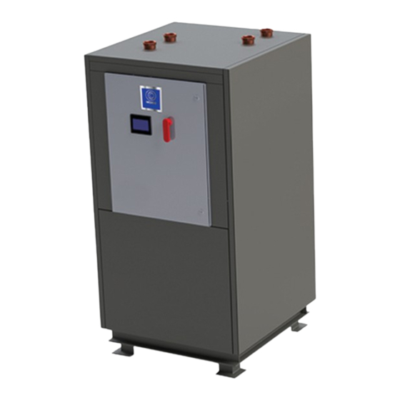
FEATURES & COMPONENTS PRODUCT ILLUSTRATION Electrical Enclosure Evaporator (Heat Exchanger) (Water to Refrigerant) Condenser (Heat Exchanger) (Refrigerant To Potable Water) Evaporator Flow Switch Hot Water Out Hot Water In Source Water Out Source Water In Compressor Filter Dryer Figure 1 Component Refrigeration Circuit Refrigerant State Component Heated Water Circuit... - Page 10 Condenser Paddle Wheel Flow Sensor Thermostatic Expansion Valve (TXV) Receiver Accumulator...
-
Page 11: Water To Water Cycle
WATER TO WATER CYCLE... -
Page 12: Rough In Dimensions
Outlet Length Width Height Rate Rate Weight Weight Water (LBS) (LBS) (GPM) (GPM) BTUH BTUH (FPT) SHPM-270 277,100 210,000 2” 34 ⅞ ” 36 ¼ ” 68 ½ ” 1,150 1,300 SHPM-540 554,200 414,450 2” 64 ¼ ” 36 ¼ ” 68 ½ ” 2,300... -
Page 13: Installation Requirements
INSTALLATION REQUIREMENTS Read all installation requirements in this manual before SOURCE WATER TEMPERATURE installation begins. ENTERING SOURCE WATER TEMPERATURE The installation must conform to these instructions and all The entering source water temperature range of operation for local and national code authority having jurisdiction. the unit is 40°... -
Page 14: Clearances
28.2 Note: Each unit is made of multiple SHPM-270 units. the above data is based on each unit having its own disconnect. the total incoming MCA and MFS are used for the power needed in the building if all units were run off of one disconnect. -
Page 15: Minimum Wire Size
MINIMUM WIRE SIZE Allowable Ampacities of Insulated Conductors Single-phase heat pump water heaters are two wire circuits. Three-phase heaters are three wire circuits. In addition to the foregoing, a grounded conductor is required. Not more than three conductors in raceway, cable, or earth (directly buried), based on ambient temperature of 30°C (86°F) TABLE 3... -
Page 16: Water Piping
Contact a local plumbing service agency to have a Water Connection and Flow thermal expansion tank installed on all closed water systems. Water Flow Rate Connection Size Unit (GPM) (Inches) MIXING VALVES SHPM-270 2” SHPM-540 2” SHPM-810 2” SHPM-1080 2” SHPM-1350 2”... -
Page 17: Contaminated Water
Mixing valves are available at plumbing supply stores. Consult a Qualifi ed Installer or Service Agency. Follow the mixing valve manufacturer’s instructions for installation of the valves. TABLE 5 TANK SELECTION CONTAMINATED WATER The HPWH unit is not an instantaneous water heater and must be connected to a storage tank. -
Page 18: Storage Recommendations
• IMPORTANT: Do not remove, cover or deface any permanent instructions, wiring diagrams, labels, or the rating label from the outside cabinet or the inside panels on the HPWH unit. FIGURE 5 • Do not tilt the unit beyond 45° at any time. All internal components are braced from the base of unit. -
Page 19: Service Tools
Heat transfer compound (paste) such as Honeywell part be evenly dispersed across the footing channels on the bottom number 107408 or equivalent. of the unit. See Table 1 on page 8 for unit dimensions and weights. Electrical switch lock out device - used to secure disconnect switches/breaker panels while servicing. -
Page 20: Water Connections
WATER CONNECTIONS 14. All components in the hot water supply system must be adequately sized to meet peak water fl ow requirement Water piping must be installed in accordance with the instructions 15. When the HPWH unit is installed above the storage tank in this manual and all local plumbing codes having jurisdiction.
Need help?
Do you have a question about the SHPM-270 and is the answer not in the manual?
Questions and answers