
Related Manuals for Tool-Temp TT-181


Summary of Contents for Tool-Temp TT-181
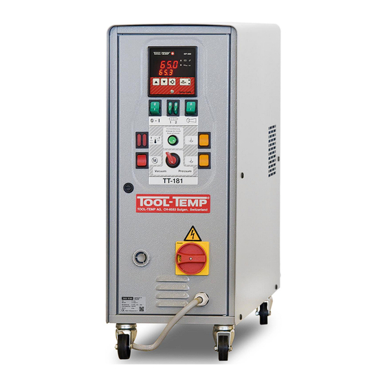
- Page 1 Manual of instruction TT-181 Temperature control unit with Temperature Controller MP-888 01/2019 Version: 04...
-
Page 2: Table Of Contents
The contents, however, do not constitute a binding obligation on the part of TOOL-TEMP AG and are subject to change without notice. In case of inconsistencies in the English translation, the German version shall prevail. - Page 3 Manual of instructions TT-181 3/33 7.1. Pump ....................................24 7.2. Heating – Temperature monitoring ........................... 24 7.3. Level control ..................................24 7.4. Temperature deviation control ............................24 7.5. Acoustic indication of faults (horn) ........................... 25 Maintenance ..........................26 8.1. Inspection ..................................26 8.2.
-
Page 4: General Safety Information
1.3. Intended Use The TOOL-TEMP temperature control unit is built according to the current state of the art and the generally accepted principles of safety engineering. The temperature control unit is intended solely for the normal use for heating and/or cooling of injection and die casting moulds, extruders, calendars, mixers and other consumers in areas in which there is no risk of explosion. -
Page 5: Safety Information
Safety Information 1.4.1. General Information The TOOL-TEMP temperature control unit is safe to operate, but this device can pose danger to life and limb if it is used incorrectly or for a purpose other than that intended. It should be noted... -
Page 6: Changing The Parameterisation
1.4.4. Changing the Parameterisation The parameterisation of the control system may only be carried out by personnel trained by TOOL-TEMP. In particular, no parameters in the device configuration may be changed without consulting TOOL-TEMP. The relevant accident prevention regulations and the generally accepted principles of safety engineering, occupational medicine and structural engineering must be observed. -
Page 7: Using This Documentation
Manual of instructions TT-181 7/33 1.5. Using this Documentation This documentation contains important information for safe, economical operation and for proper maintenance of the device. Compliance with this documentation helps to avoid danger, minimise repair costs and downtime, and increase the dependability and service life of the unit/system. -
Page 8: Overview Temperature Control Unit
Manual of instructions TT-181 8/33 2. Overview temperature control unit 2.1. Front view... - Page 9 Manual of instructions TT-181 9/33 Temperature Controller MP-888 ON/OFF-Switch unit (green) ON/OFF-Switch heating (green) Water: Switchable in stages 3 kW + 6 kW = 9 kW Oil: 3 kW (OR-circuit) ON/OFF-Switch horn (green) Temperature monitoring internal left (red) The maximum temperature of the unit is exceeded. The unit switches off.
-
Page 10: Rear View
Manual of instructions TT-181 10/33 2.2. Rear view ½“ BSP female thread From mould Manometer pump pressure ½“ BSP female thread To mould ⅜“ BSP female thread Cooling water inlet with water filter ⅜“ BSP male thread Cooling water outlet Manually refill with overflow 1“... -
Page 11: Identification Of Residual Risk On The Unit
Manual of instructions TT-181 11/33 2.3. Identification of residual risk on the unit On the temperature control unit following pictograms are mounted to identify the residual risk. DANGER The temperature control unit must be rendered currentless before it is opened! Turn off the main switch on the temperature control unit and... -
Page 12: Technical Specifications
Manual of instructions TT-181 12/33 3. Technical Specifications Temperature range up to 90°C with water / up to 150°C with oil Temperature control self-optimizing, electronic microprocessor controller MP-888 Heating capacity Water operation: 9 kW, with manual stage switching 3/6 Oil operation:... -
Page 13: Eu - Declaration Of Conformity
Manual of instructions TT-181 13/33 4. EU – Declaration of conformity... -
Page 14: Installation
Manual of instructions TT-181 14/33 5. Installation Before starting the unit the electrical and hydraulic connections have to be installed. The installation of the unit has to be done in the order of the following chapters. After the proper installation the unit is ready to use. -
Page 15: Connections
Manual of instructions TT-181 15/33 The temperature control unit is designed for an ambient temperature of +10 up to 40°C. Sufficient ventilation must be ensured during set-up. The distance between the temperature control unit and other facilities must be at least 10cm. The ventilation opening must be free. -
Page 16: Power Supply
Manual of instructions TT-181 16/33 For the cooling water connections it’s enough to use pressure- and temperature-resistant rubber hoses. The tap water pressure has to be between 2,0 and 5,0 bar. We recommend to conduct the water from the unit (cooling water outlet) to an unpressurized outlet. -
Page 17: Pump Rotation Check
Manual of instructions TT-181 17/33 5.4.1. Pump rotation check At the rear side of the unit the direction of rotation can be checked. The unit has been connected to the main supply, hoses must be mounted and heat transfer medium has been filled. Identify the sense of rotation of the motor by switching it on shortly. -
Page 18: Initial Operation With Heat Transfer Oil (Oil Operation)
Manual of instructions TT-181 18/33 5.5. Initial operation with heat transfer oil (Oil operation) The temperature control unit can also be operated with heat transfer oil. The unit must be prepared accordingly for this operation and after this the unit can be filled manually through the filler neck. A guideline for the required filling amount can be taken from the technical data. -
Page 19: Operations
Manual of instructions TT-181 19/33 6. Operations The unit is controlled by the temperature controller MP-888. The temperature controller MP-888 is a universal controller for all TOOL-TEMP units. 6.1. Overview MP-888 Display of set value Display of actual value Flow control Display of the current flow in litres/min, English or American gallons/min. - Page 20 Manual of instructions TT-181 20/33 Technical specifications Temperature sensor connection Temperature sensor – note + / - 21+23 Pt-100 compensation Flow control – encoder signal Connection external set point 26+28 Analog input 4 - 20mA 27+28 Analog input 0 - 10 V...
-
Page 21: Parameter Settings Mp-888 - Without Flow Control
Manual of instructions TT-181 21/33 Parameter settings MP-888 – without flow control 6.2. Each unit requires a different programme setting. For each model is a programme defined that not every parameter must be set manually. In this program the model specific settings are saved. - Page 22 Manual of instructions TT-181 22/33 Temperature 400.0°C / 752°F Upper scaling point of the voltage at 20 mA INPUT analog input (-49.9…400.0°C) (-57.8…752.0°F) 20 mA corresponds to 400°C Temperature 0.0°C / 32.0°F Lower scaling point of the voltage at 0 V OUTPUT analog output (-50.0…399.9°C)
-
Page 23: Setting Of The Temperature - Heating / Cooling
Manual of instructions TT-181 23/33 Setting of the temperature – Heating / Cooling 6.3. The required temperature on the temperature controller can be adjusted with the arrow buttons. The heating mode is indicated by the red diode on the temperature controller. The unit can only heat when the 0-1 switch (heating) is active. -
Page 24: Safety And Monitoring Devices
Manual of instructions TT-181 24/33 7. Safety and monitoring devices 7.1. Pump The pump motor is fitted with an overload relay and pre-switch automatic cut-outs. Heating – Temperature monitoring 7.2. In the temperature controller the maximum temperature (150°C) is limited. Exceeding this temperature the heaters switch off. -
Page 25: Acoustic Indication Of Faults (Horn)
Manual of instructions TT-181 25/33 7.5. Acoustic indication of faults (horn) In order to perceive faults immediately serves a horn. If the level in the tank drops, the horn rings with a continuous sound (pre-warning). The temperature control unit still operate. The tank volume has to be corrected. -
Page 26: Maintenance
Manual of instructions TT-181 26/33 8. Maintenance Inspection and maintenance have to be done by instructed staff (competent). The following maintenance intervals may be required subject to use and environment: Water filter clean / replace every month Pump motor blow out the fan... -
Page 27: Out-Of-Service / Transport
Never transport the unit lying – Lying transport will destroy the unit! 10. Disposal The temperature control unit must be drained completely and disposed of in accordance with local regulations. The temperature control unit can also be returned to TOOL-TEMP for disposal. -
Page 28: Failure Corrective Action
Manual of instructions TT-181 28/33 11. Failure corrective action Symbol Symptom Probable cause Correction • Fuse defective • Replace the 5 x 20 mm 1 A Green ON/OFF-switch as well as all lamps do not fuse • Possibly transformer or light •... -
Page 29: Components And Spare Parts
Manual of instructions TT-181 29/33 12. Components and spare parts 12.1. Overview components and spare parts... - Page 30 Manual of instructions TT-181 30/33...
-
Page 31: Liste Komponenten Und Ersatzteile
Manual of instructions TT-181 31/33 12.2. Liste Komponenten und Ersatzteile Art.-Nr. ELS-Code Bezeichnung Bemerkung 1 Fa0800326 Digital temperature controller MP-888 Fa0800328 Digital temperature controller MP-888 revised 2 Fa0900003 Fixing clips for controller MP-888 As a pair incl. straining screw 3 Wa1000030 B 1... - Page 32 Manual of instructions TT-181 32/33 380 – 415V 50Hz Pump type E with pump motor 0.75kW 200 – 230V 50Hz Pump type E with pump motor 0.75kW Pump type E with pump motor 0.75kW 380V 60Hz 200 – 230V 60Hz 440 –...
- Page 33 Manual of instructions TT-181 33/33 Solenoid valve R1/4“ (18bar) 31 Df0200110 Y 15 mould drain Repair kit for solenoid valve R1/4“ (18bar) Df0200910 Composed of: spring and plug Df0200600 Magnetspule 230V 50/60Hz Ø 12 mm 32 De0701600 Manometer -1 bis 6 bar Ø...
Need help?
Do you have a question about the TT-181 and is the answer not in the manual?
Questions and answers
Not heating up
The Tool-Temp TT-181 may not be heating up due to several possible reasons:
1. Maximum Temperature Exceeded: If the set temperature exceeds 150°C (for oil) or 90°C (for water), the heating function becomes inactive, and the maximum temperature LED lights up.
2. Temperature Deviation Alarm: If the actual temperature differs significantly from the set temperature, an alarm may activate, preventing heating.
3. Power Supply Issue: Ensure the unit is connected to a proper 230V AC power source and that the electrical connections are intact.
4. Faulty Heating Element: The heating element may be defective and require inspection or replacement.
5. Blocked Flow or Leak: If there is a blockage in the system or a leak, the unit may not function correctly.
6. Incorrect Parameter Settings: The unit's program settings (P41 for TT-181) should be checked to ensure they are correctly configured.
7. Cooling Command Active: If the cooling function is active, it may prevent the heating function from working.
To resolve the issue, inspect the power supply, temperature settings, alarms, and heating element, and check for any blockages or leaks.
This answer is automatically generated