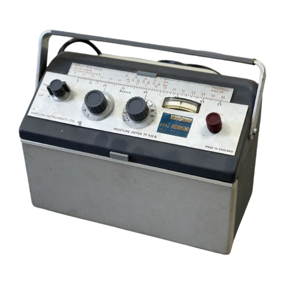
Summary of Contents for Marconi TF 933B
- Page 1 Instruction Manual No. EB 933B Moisture Meter TF 933B rechn•cal MARCONI INSTRUMENTS LIMITED ST. ALBANS HERTFORDSHIRE ENGLAND C. P. Z. 2k 3/68/ A...
-
Page 2: Table Of Contents
Contents Chapter General information 1.1 FEATURES Chapteri GENERAL INFORMATION 1. 1 Features The moisture meter measures the percentage moisture content of a wide 1.2 Data summary of hygroscopic materials, particularly those of organic origin, in the field or i 1.3 Accessories The test cell which is of the compression type and is stowed in the instn Chapter 2 OPERATION when not in use, is suitable for granular, powdery or fibrous substances and ft... - Page 3 Paper: 4 to 13% for paper; 6 to 22% for chemic pulp and boards. Temperature 10 to 3: IIANGF,: Moisture contents from below air-dry to near to 90 O F). Supplementary information provided covering many types of wood p saturation. paper and boards.
- Page 4 MARY Paper: 4 to ror paper; G to for chen pulp and boards. Temperature 10 to RANGE: Moisture contents from below air-dry to near to 90 O F". Supplementary informatic saturation. provided covering many types of wooc paper and boards. The scales are b: oven drying to constant weight at 102 ACCURACY:...
-
Page 5: Accessories
Small hand -operated Mill TB 40884; for grinding whole grain etc. Spare Standard Electrode TM 4178A; ror ccmpresgion cell electrode am Large Electrode Unit TM 4178M3 (compiete with Ring TC 22433/1 and F TC 22433/2); for use with compression cell electrode to accommodate The unit hag a diameter of about 2 inches and holds about 10 | samples. -
Page 6: Chapter 2 Operation
Chapter Operation 2.1 INSTALLATION NOTE: The performance of this instrument may be impaired by length' exposure to a damp atmosphere. Drying for a short period in warm dry atmosphere will restore it to give normal performar Check that the dry batteries (67.5 V and 1.5 V) are correctly positioned regard to polarity, as shown by the battery cover plate. -
Page 7: Preparation Of Sample
ed CA LIBRATION CHECK are provided for connection to :s-ocketn for test purpogeg. tor scales Jf a scale is availablc for the gub8tance to be tested glidc the scale into position - nee Fig. 1.1. If tbcrc is no aca)e available then gclcct the appropriate calibration data sheet. -
Page 8: Reading The Instrument
p. Withdraw the test cell. Take out the plunger. Sheets and boards (e.g. cardboard) the insulating ring is well geo ted on the electrode. In handling the The ring and plunger of the test cell are not required for these materials hold by the edges. -
Page 9: Avoiding Errors
ens' clial (left-hand BALANCE knob) should not be on the O e ,' St'OlNG PEO SHOW", position when setting zero. As this is thc most sensitive range, MOISTURE traces of leakage due to atmospheric humidity and effect of electro- 8tatic induction may cause the reading to be a little unsteady. Switch to any lunge other than O to set zero. -
Page 10: Chapter 3 Technical Description
ror is not acceptable it may be possible to save time by gently Chapter cell to match the temperature of the grain. Technical description Temperature difference between Total inaccuracy cell and sample, o c go moisture content 1.0% 3.1 CIRCUIT DESCRIPTION 1.6% The electrical measuring circuit as shown in Fig. -
Page 11: Chapter4 Maintenance
The dial reading should be 60. clamp down on a piece of metal foil. The diagram Fig. 4. 1 illustrates the accessibility of the components Moisture Meter TF 933B. Leakage Access to the replaceable parts such as the dry batteries and the vall Having checked continuity as above, unscrew the clamp and secure the electrode the fitting of the a. -
Page 12: Changing The Batteries
NOTE: On moiBture metero dispatched without batteries tho internal batt cover is fitted in tho front cover of the lower 8townge compartme 4.6 CHANGING THE BATTERIES The 67,5 V battery *hould be changed every year. Tho 1.5 V batterieg al last for about 100 working hours - correaponding to about G months une if the int Even if not used to thin extent they shout( ment is switched off when not in use. - Page 13 procedure is the same for both voltage ranges. Chapter Replaceable parts Release the slotted screws securing the carrying handle to the upper half of the instrument case and ease back the upper half of the case, taking care to provide suitable support.
- Page 14 Circuit reference Descrtption M.I. code Battery 67.5V (Exide DM501 or Ever Ready BIOI or Vidor L5500) 23721-543 Battery 1.5V (Exide T21 Ever Ready 1,mJ2 or Vidor IN2) 2 3711 —105 Battery 1.5V (Exide T21 Ever Ready LHJ2 or Vidor LP12) 23711-105 Mains Unit TM 9689 Plas 330pF...
- Page 15 Circuit diagrams Circuit notes COMPONENT VALUES Resistors: no suffix = ohms, k = kilohms, M = megohms. Capacitors: no suffix = microfarads, p = picofarads. value selected during test, nominal value shown. not used on TF9JJB SYMBOLS arrow indicates clockwise rotation of knob. etc.
- Page 16 fig. 2.2 A.CA mains unit...


Need help?
Do you have a question about the TF 933B and is the answer not in the manual?
Questions and answers