
Summary of Contents for GENPOWER FORTRUST 6110D
- Page 1 FORTRUST 6110D/ 6120D CONTROLLER USER MANUAL This document provides a brief operation instruction for using GEC6100D series controllers.
-
Page 2: Key Descriptions
1. MODELS: Model Function It is used for single machine automation, controlling the start and stop of genset by remote GEC6110D signal. GEC6120D It adds the functions of mains monitoring and AMF on the basis of GEC6110D. 2. KEY DESCRIPTIONS: In manual/ auto mode, it stops the running genset. -
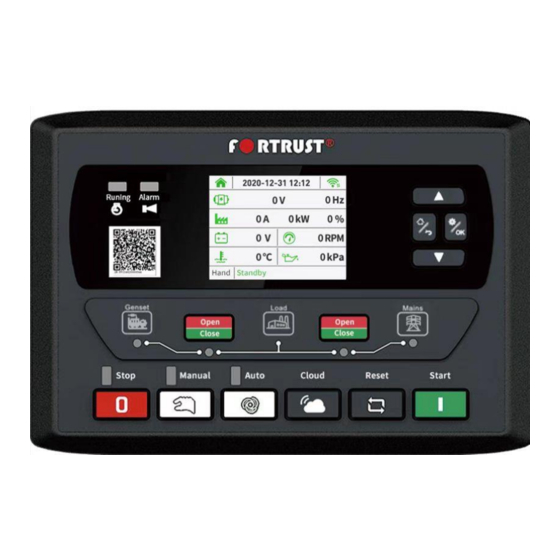
Page 3: Controller Panel
Press this key to enter the cloud service mode. Press this key to enter the Interface of WIFI connection with TWO-DIMENSIONAL code. Press it Cloud Service again to exit and enter the main interface. This key only takes effect on the home page of the controller. - Page 4 GEC6120D 5. SETTINGS: Settings Menu: 1) After the controller starts up, press the button to enter the settings menu. 2) Press the cursor (up/ increase) or (down/ decrease)to select the controller’s information. 3) Press the button to enter the password settings interface. 4)...
- Page 5 6) Press the button (home/ return) to return to the previous menu. CAUTION! The value that entered in parameters should be between within range otherwise it will not be saved. Work Calendar Settings: When the main switch of work calendar is enabled, the setting of start and stop time of work calendar is effective;...
-
Page 6: Parameter Setting
6. PARAMETER SETTING: Parameter Range Default Description Mains Normal Delay (0-3600)s The delay from abnormal to normal or from normal to abnormal. It is used for ATS (Automatic Transfer Switch) Mains Abnormal Delay (0-3600)s control. (30-60000) When mains voltage is lower the value, mains under Mains Under Voltage voltage is active. - Page 7 Parameter Range Default Description Solenoid’s power-on time while genset is stopping. 17(12) ETS Solenoid Hold (0-120)s If “ETS Solenoid Hold” set as “0”, it is the time from end of idle delay to genset at rest; if not “0”, it is from end of 18(13) Fail to Stop Delay (0-120)s...
- Page 8 Parameter Range Default Description When the oil pressure sensor value is under this point, Low Oil Pressure alarm is sending out. When the value is “0”, warning alarm won’t be sent. (This function is only suited 31(26) Low Oil Pressure (0-400)kPa for oil pressure sensor, except for low oil pressure alarm signal inputted by programmable input port.)
- Page 9 Parameter Range Default Description 48(43) Aux. Output 4 Function (0-25) Factory default: Mains closed. See 7. Outputs Title. Factory default: High temperature alarm input. 49(44) Aux. Input 1 Function (0-25) See 8. Inputs Title. 50(45) Aux. Input 1 Valid (0-1) Factory default: Closed.
- Page 10 Parameter Range Default Description High Temp. Stop Default: When temperature is overheat, the genset alarms 70(65) (0-1) Inhibit and shutdown. Low OP Stop Default: When oil pressure is too low, the genset alarms 71(66) (0-1) Inhibit and shutdown. 0 3 Phase 4 Wire (3P4W) 72(67) AC system (0-2)
- Page 11 Parameter Range Default Description It is the speed-drop pulse output time, when the unit begin 88(83) Speed Drop Pulse (0-20.0)s to idling for stop. 89(84) ATS Open Time (1.0-60.0)s It is duration to open ATS. 0 User-defined temperature sensor, 1 User-defined pressure sensor, 2 User-defined level sensor, (0-2)...
- Page 12 7. OUTPUTS: Parameter Description Not Used Output is disabled when this item is selected. This output includes all shutdown alarm and warning alarm. When warning alarm occurs, the alarm won’t self-lock; when a shutdown Common Alarm Output alarm occurs, the alarm will self-lock until alarm is reset. This output valid for gen-sets with stop solenoid.
- Page 13 Parameter Description Reserve Reserve Reserve Reserve Speed Raise Pulse Active while the unit entering into high-speed warming up. Output Speed Drop Pulse Active while the unit entering into stop idling. Output Activated when the fuel level lower than the open threshold or low fuel Oil Pump Control level warning is active;...
- Page 14 Parameter Description Inhibit OPL STOP When it is active, low oil pressure stop is inhibited. In Auto mode, when input active, gen-set can start and take load after Remote Start gen-set is OK; when input inactive, gen-set will stop automatically. Low Fuel Level Warning Connected to sensor’s digital input.
- Page 15 Parameter Description User Set 1 Input can be customized by user. User Set 2 Input can be customized by user. 9. SENSORS: Parameter Options Description 0 Not Used 1 Defined Curve 2 VDO 3 SGH 4 SGD Defined input resistance range is; Temp.
-
Page 16: Cloud Service
10. CLOUD SERVICE: Connection Sign Cloud Key A. The Cloud button provides remote access to your controller, thus to your generator, with your mobile phone. B. By connecting to the controller wirelessly from your mobile phone via an application you can download to your phone, you can monitor the status and alarms of your generator, request service assistance, and set its parameters. - Page 17 CAUTION! After downloading the application to your mobile phone, allow the application to use location services! Step 2: Open the app with “ ” icon on your mobile phone. Press the “Cloud” key on your controller. Scan the QR code on the screen that opens by pressing the camera button in the upper left corner of the application on your mobile phone.
- Page 18 In wireless networks, click on the wireless network name starting with FM code and enter the password, After downloading the application, the wireless connection between your mobile phone and your controller will be established. Step 4: On the main page of your controller, the “ ”...
- Page 19 F. You can share fault conditions or operating curves and information with the service over “Cloud”. CAUTION! After the connection between the mobile phone and the controller is established, the synchronization takes approximately 90 seconds takes. G. By pressing the “Calibration Data” button at the bottom of your application, you can change all the parameters of your controller from your mobile phone;...
- Page 21 11. EXTERNAL CLOUD SERVICE AND DEVICE (MODEM): External Cloud Service provides remote access, monitoring and remote control to your controller. External Cloud device; it can be added to the controller, a data sim card can be inserted into it, so over satellite and internet; It is an additional device that allows connection to the controller with a mobile phone, tablet, laptop or desktop computer from anywhere in the world, regardless of distance.
- Page 22 B. For remote access to the controller with a external cloud device from a mobile phone ; Download the application to your mobile phone by scanning the QR code below with your phone's camera, Go to www.fortrustyun.com website, ...
- Page 23 Start using remote access by entering your user name and password on the main screen of the mobile phone application. 12. CONTROLLER AND EXTERNAL CLOUD DEVICE CONNECTION: External Connection: Step 1: According to the wiring diagram, connect RS485 to GPS and 4G signal. Step 2: Open the front cover, insert the sim card into the slot and close the cover again.
- Page 24 Step 3: Connect the antenna cables. Make sure to connect the 4G signal to the socket shown in red and the GPS antenna to the socket shown in blue as shown below. B. External Cloud Device Indicators:...
- Page 25 Symbol Definition Description POWER POWER On:Successfully powered on Off:Network registration failed On:Network registration succeeded Flashing:Data upload normal On:GPS not powered on Location On:GPS not located Flashing:GPS got satellite signals Off:RS485 not used RS485 RS485 On:Communication failed Flashing:Communication normal Off:CAN not used On:Communication failure Flashing:Communication normal Off:LIN not used...
- Page 26 C. Installation Dimensions: Cloud module can be installed by either guide rail or screw. The guide rail supports 35mm, and screws is M3.
-
Page 27: Typical Application
13. TYPICAL APPLICATION: GEC6110D GEC6120D...
Need help?
Do you have a question about the FORTRUST 6110D and is the answer not in the manual?
Questions and answers