
Subscribe to Our Youtube Channel
Summary of Contents for LAGO Basic 0201 R V1
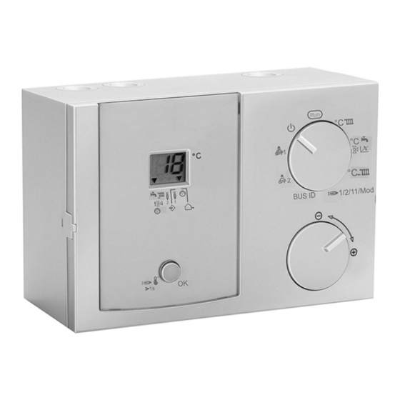
- Page 1 Lago Basic 0201 R V1 Heating module Operating and Installation Instructions Please observe the safety instructions and read through this manual carefully before commissioning the equipment.
-
Page 2: General Information
Explanation of the operating elements Operation General information Description Safety information Declaration of conformity Power connection regulations Please note the connection conditions specified by your local electrical power supply utility and the VDE regulations. Your heating control system may be installed and serviced This device corresponds to the requirements of the only by appropriately authorised specialists. -
Page 3: Table Of Contents
Assembly / Dismantling General information General information Functions Safety information Operation in the cascade Power connection regulations Modulation in the cascade Warranty conditions Operation of a single heat generator Important text passages Stand alone Installation Single HS with Manager via CAN BUS Modulation via air damper Description Frost protection function... -
Page 4: Operation
Explanation of the operating elements Operation H 1/2/11/Mod Operation heat generator stages Explanation of the operating elements (1=single stage, 2=two-stage, 11=2HS, m=modulating) Selection switch *) Pump ON > [°CD+5K v 65°C]; OFF < [°CD-5K v Automatic mode 55°C] Standby (frost protection only) Rotary knob burner OFF, pump OFF •... -
Page 5: Display (Normal Mode "Run")
Assembly / Dismantling General information Symbols below the display with return flow temperature increase With return flow temperature increase sensor and mixer dynamic > -- Selection switch = Mixer OPENS (arrow points upward) = Mixer CLOSES (arrow points downward) With return flow temperature increase sensor and mixer dynamic >... -
Page 6: Starting Up
Explanation of the operating elements Operation Starting up List of the User Set Values Starting up Designation Area Factory After the device has been properly installed, switch on the power supply. Run => Normal mode Display level with rotary knob The software number for your device and then the index of your software briefly appears in the display. -
Page 7: Explanatory Information
Assembly / Dismantling General information Small values cause the mixer to adjust quickly and can Explanatory information Set values lead to oscillation. °C Flow set temperature (fixed value) Modulation (H 1/2/11/Mod = m) Stand-alone or individual heat generators => Mixer Display of the maximum flow temperature dynamics for air damper control Without BUS: Input or the desired flow temperature. -
Page 8: Settings Via Dip Switch (Rear Side)
Explanation of the operating elements Operation Settings via DIP switch (rear side) used to actuate any of the following configurations: • A single stage heat generator with associated Settings 1-5 => In V1 without function boiler pump and return flow temperature increase Sensor selection (5K NTC <- >... -
Page 9: Operation Of A Single Heat Generator
Assembly / Dismantling General information and during the first three minutes after "Burner ON", the air Operation of a single heat generator damper is constantly driven towards in "CLOSE" direction. Settings: Connection 1/2/11/Mod = m (Modulation) 1/2/11/Mod = 1 (switching heat generator) During this operating condition, the relays T3 T4 is BUS-ID = -1 (single HS with desired temperature switched in parallel with the HS pump =>... -
Page 10: Frost Protection Function
Explanation of the operating elements Operation temperature or [burner OFF and after-run time of pump Frost protection function has elapsed]. The frost protection circuit prevents the heating system from freezing by automatically switching on the pump. EEPROM check Flow sensor frost protection Every 10 minutes, a check is conducted automatically in The frost protection function is activated if the flow order to establish whether the settings of the controller lie... -
Page 11: Installation
Assembly / Dismantling General information Installation Installation Assembly / Dismantling 3 x 0,5... -
Page 12: Electrical Connection Controller
Explanation of the operating elements Operation Electrical connection Controller 230V∼; Relay switching capacity 2(2)A, 250V∼ Safety extra-low voltage 1+2 Burner 1 (floating contact) 5 Mixer OPEN / 13-16 CAN BUS HS2 pump 6 Mixer CLOSE / 17+18 Sensor for HS2 Return flow temperature increase (= Boiler 2) KF2 pump... -
Page 13: System Diagrams
Assembly / Dismantling General information System diagrams HS controller in cascade operation Heat generator with temperature sensor KF and switch input T1 T2 HS pump (possibly in heating circuit flow) Return flow sensor VF Mixer (Temperature increase of return flow by mixer) Pump (Temperature increase of return flow by... -
Page 14: Sensors
Explanation of the operating elements Operation Sensors Outdoor sensor AF S Flow sensor VF v Installation location: Installation location: • Wherever possible, on a northerly or north-easterly • In the case of boiler control instead of the boiler sensor wall behind a heated room KF as close as possible behind the boiler on the •... -
Page 15: Sensor Values / Characteristic Curve
Assembly / Dismantling General information Sensor values / characteristic curve Errors Temperature 5Kohm NTC 1Kohm PTC Ω Ω -60°C 698961 When there is an error, the corresponding error number Ω Ω -50°C flashes. 333908 Ω Ω -40°C 167835 Ω Ω -30°C 88340 Error no. -
Page 16: Technical Data
Explanation of the operating elements Operation Technical data Supply voltage complying with 230 V AC ± 10% DIN IEC 60 038 Power consumption Max. 5 VA Switching capacity of the relays 250 V AC 2(2) A Switching capacity Triac (T3/T4) 250V AC 1,2(1,2) A Maximum current on terminal 6.3 A Type of protection complying...
Need help?
Do you have a question about the Basic 0201 R V1 and is the answer not in the manual?
Questions and answers