NETGEAR ProSafe GSM7328 Installation Manual
Stackable managed switch
Hide thumbs
Also See for ProSafe GSM7328:
- Administration manual (118 pages) ,
- Brochure (2 pages) ,
- Application note (16 pages)
Advertisement
Quick Links
Download this manual
See also:
Administration Manual
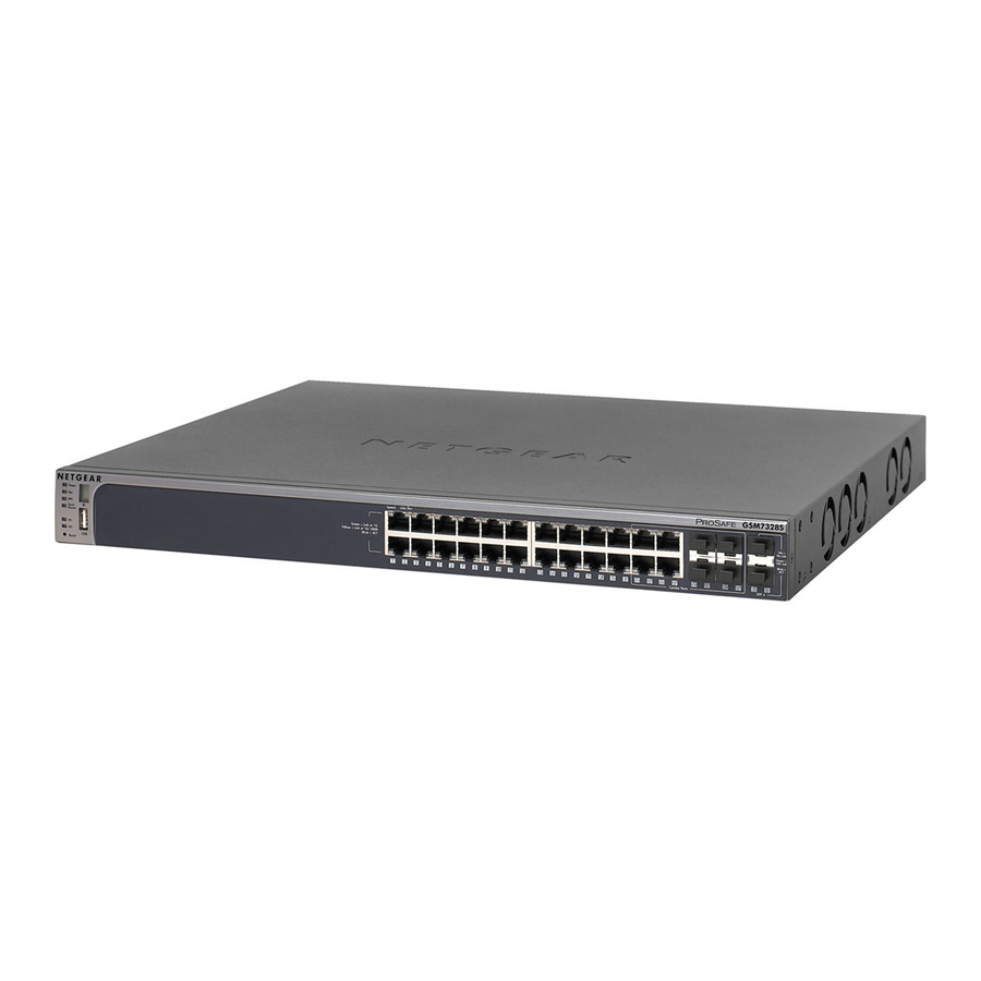
7300S Series Stackable Managed Switch
Follow these quick steps to install your switch.
You can also consult the full hardware installation guide on the Resource CD.
Verify the Following Package Contents
•
7300S Series Stackable Managed Switch
•
Rubber footpads for tabletop installation
•
Power cord
•
Null-modem console cable
•
Rack-mount kit for installing the switch in the rack
•
This Installation Guide
•
CD ROM
•
Warranty and Support Information Cards
If any item is missing or damaged, contact your place of purchase immediately.
Set Up the Switch
Prepare the site so that the mounting, access, power source, and environmental
requirements identified in the Hardware Installation Guide published on the CD-ROM are
met.
1.
Install the switch.
•
Installing the Switch on a Flat Surface: Stick one of the rubber footpads that
came with the switch on each of the four concave spaces on the bottom of the
switch.
•
Installing the Switch in a Rack: Use the rack-mount kit supplied with your
switch.
2.
Apply AC Power
When you apply power, the Power LED on the switch's front panel will be Yellow, as
it conducts a Power On Self Test (POST). After the switch passes the POST, the
Power LED will change to Green and the switch is functional and ready to pass data.
If the POST fails, the Power LED will stay Yellow.
If the Power LED does not go on, check that the power cable is plugged in correctly
and that the power source is good. If this does not resolve the problem, refer to
Appendix B, Troubleshooting, in the Hardware Installation Guide on the CD-ROM.
3.
Connect Devices to the Switch
Use Category 5 (Cat5) cable to connect devices.
SFP modules ship separately. If you need instructions on installing an SFP module,
please refer to the Hardware Installation Guide on the CD-ROM.
Perform the Initial Configuration
To configure the IP address, you must first access the Command Line management utility
via the console interface. You can connect to it using a VT100/ANSI terminal or a PC,
Apple Macintosh, or UNIX workstation that is directly connected to the switch's console
port.
Establish a Console Session and Log In to the Switch
1.
To connect a console to the switch:
•
Using the null-modem cable supplied with the switch, connect a VT100/ANSI
terminal or a workstation to the switch port labeled Console.
•
If you attached a PC, Apple Macintosh, or UNIX workstation, start a terminal-
emulation program:
•
Windows users can use HyperTerminal.
•
Macintosh users can use ZTerm.
•
UNIX users can use a terminal emulator like TIP.
2.
Configure the terminal-emulation program to use the following settings:
•
Baud rate: 9,600 bps
•
Data bits: 8
•
Parity: none
•
Stop bit: 1
•
Flow control: none
These settings appear below the connector on the switch front panel.
3.
The switch is shipped using DHCP protocol by default, so that the management IP
address is assigned automatically from a DHCP server. To see the assigned IP
address, log in to the switch with the user name of either admin or guest, and type the
show network command. If you wish to assign the switch IP address manually,
please use the procedure that follows.
Advertisement

Related Manuals for NETGEAR ProSafe GSM7328


Summary of Contents for NETGEAR ProSafe GSM7328
- Page 1 DHCP server. To see the assigned IP address, log in to the switch with the user name of either admin or guest, and type the show network command. If you wish to assign the switch IP address manually,...
- Page 2 ©2005 by NETGEAR, Inc. All rights reserved. NETGEAR is a registered trademark of NETGEAR, Inc. in the United States and/or other countries. Other brand and product names are trademarks or registered trademarks of their respective holders. Information is subject to change without notice.
Need help?
Do you have a question about the ProSafe GSM7328 and is the answer not in the manual?
Questions and answers