Table of Contents
Advertisement
Quick Links
Advertisement
Table of Contents

Related Manuals for EML Kalyx-RG

Summary of Contents for EML Kalyx-RG
- Page 1 Wind Speed & Direction Sensor User Manual UM-975-001-WSD1 Manual – V2.1...
- Page 2 The contents are subject to change without prior notice. Please observe that this manual does not create any legally binding obligation for EML towards the customer or end user. All legally binding commitments and agreements are included exclusively in the applicable supply contract or Conditions of Sale.
-
Page 3: Table Of Contents
Table of Contents List of Figures ............................4 List of Tables ............................4 General Information ........................5 About this Manual ..........................5 Version Information ........................5 Related Manuals ..........................5 Introduction ............................ 6 Site and Installation Requirements ....................6 Choosing a site ............................ 6 Wiring &... -
Page 4: List Of Figures
List of Figures Figure 1 - Wiring diagram of WSD1......................7 Figure 2 - Mast assembly detail ......................11 Figure 3 - Guy wiring detail ........................13 Figure 4 - Assembled WSS1 ........................14 Figure 5 - Assembled WSS2 kit ......................16 List of Tables Table 1 - Document Revisions ......................... -
Page 5: General Information
1. General Information About this Manual This manual is intended as a general guide for installing, wiring and using a Kalyx-RG rain gauge. The information contained in this manual may not cover all aspects of Kalyx-RG applications. Please refer to associated equipment manuals or consult papers and technical notes on the EML website (www.emltd.net). -
Page 6: Introduction
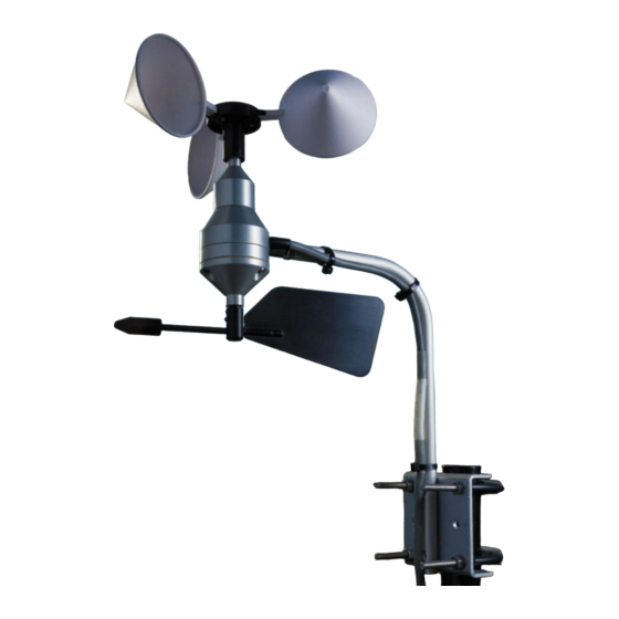
2. Introduction The WSD1 sensor measures both wind speed and wind direction. At the top of the unit is a 3-cupped anemometer (white) for measuring wind speed, and at the bottom, a wind vane (black) for measuring wind direction. Always ensure that this orientation is maintained. These devices are attached to the main body of the unit which is made of a clear anodised (HT30) aluminium alloy. -
Page 7: Wiring & Connection Information
4. Wiring & connection information This section gives information on connecting the WSD1 to loggers, including a circuit diagram. Wiring colours. The cable supplied with the WSD1 sensor consists of three twisted pairs of inner conductors plus a screen. The screen is not connected within the sensor. The fitted twisted-pair cable consists of one colour plus its associated black. -
Page 8: Additional Technical Information
5. Additional Technical information This section provides technical specifications for the WSD1 and the cable. Technical Specifications of the WSD1 Speed Sensor Calibration 1 contact closure / 1.493m Reed detector Bench tested to a minimum speed of 90m/s. Start-up 0.5 m/s typically. Accuracy Linearity Contact Rating... -
Page 9: Speed Component Of The Sensor (Anemometer)
Speed component of the sensor (anemometer) The use of this design also allows the anemometer to be used in circuits down to zero voltage and current, without reducing the life expectancy of the reed switch. In the circuit diagram shown in Figure 1 a 100 ohm resistor is fitted into the wiring. This is because in long cable runs the capacitance between conductors is appreciable. -
Page 10: Assembly And Use Of The Wss1
6. Assembly and use of the WSS1. The WSS1 consists of a WSD1 sensor plus a full mast kit for mounting the head at the standard two metres height. It is of a lightweight aluminium construction and suitable for temporary or permanent use. -
Page 11: Figure 2 - Mast Assembly Detail
MAST ELBOW ADAPTOR (C) MOUNT (b) JOINER (e) M4 SET M4 SET SCREWS SCREWS SCREWS UPPER MAST TUBE (d2) LOWER MAST M6 WASHERS TUBE (d1) M6 BOLT M6 NUT BASEPLATE (f) Figure 2 MAST ASSEMBLY IN DETAIL Figure 2 - Mast assembly detail UM-975-001-WSD1 Manual –... -
Page 12: Final Assembly
Final assembly If the system is being assembled in the field then the four steel pegs should be fitted through the corners of the Baseplate (f) and into the ground. They may require knocking in with a mallet. Assemble an M6 bolt and washer through the hole in a stake (k), fit another washer and then the first shoulder nut as shown in Figure 3, and fully tighten. -
Page 13: Figure 3 - Guy Wiring Detail
GUY WIRES KIT (g) M6 BOLT WASHERS FIT EYE OF THE GUY TENSIONER HERE SHOULDER NUTS MOUNTINGS IN CLOSE-UP STAKE (k) Figure 3. GUY WIRES IN DETAIL Figure 3 - Guy wiring detail UM-975-001-WSD1 Manual – V2.1 13 | P a g e... -
Page 14: Figure 4 - Assembled Wss1
NORTH Figure 4 THE ASSEMBLED WSS1 KIT Figure 4 - Assembled WSS1 UM-975-001-WSD1 Manual – V2.1 14 | P a g e... -
Page 15: Assembly And Use Of The Wss2
7. Assembly and use of the WSS2. The WSS2 product consists of the WSD1 sensor plus a simpler mounting than the WSS1 kit, used when fixing to masts or poles of up to 2" (50mm) in diameter. The mount is a clear-anodised alloy. Unpacking and Assembly Unpack and identify all parts of the WSS2 kit from the box by using Table 5 and Figure 5. -
Page 16: Figure 5 - Assembled Wss2 Kit
M8 STUD NORTH Detailing alternative horizontal mounting Figure 5 THE ASSEMBLED WSS2 KIT Figure 5 - Assembled WSS2 kit After aligning, tighten the clamps to stop the assembly from rotating. Cable ties should be fitted to ensure a tidy cable run down the mast. If the WSS2 kit is being fitted to a horizontal mast then the two M6 screws (e) should be removed, the bracket rotated 90 o and the screws replaced and fully tightened. -
Page 17: Appendix A - Wind Sensor Products And Spares
Appendix A – Wind sensor products and spares Table 6 – Wind sensors products Product code Description W-975-001 WSD1 Wind Speed & Direction Unit W-975-002 WSS1 Wind Speed & Direction Unit + Mast W-975-003 WSS2 Wind Speed & Direction Unit + Bracket W-975-010 WSU1 Wind Speed Unit W-975-011...
Need help?
Do you have a question about the Kalyx-RG and is the answer not in the manual?
Questions and answers