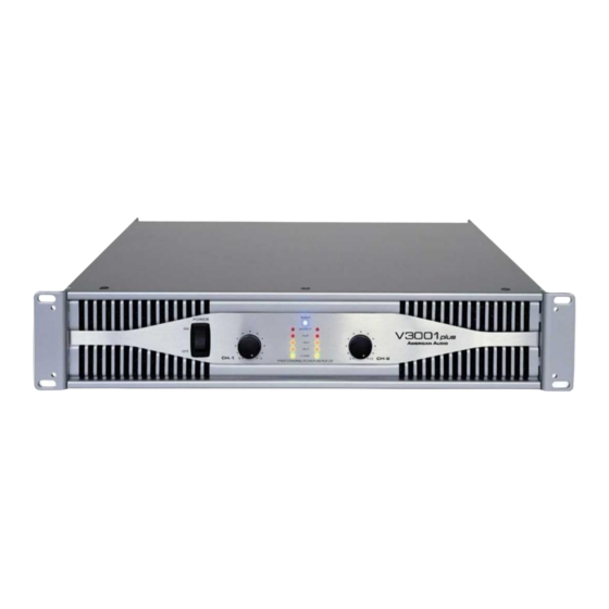
Summary of Contents for ADJ V3001 Plus
-
Page 1: Table Of Contents
All manuals and user guides at all-guides.com SERVICE MANUAL V3001 Plus MODEL NO.:V3001 Plus Contents Specification Block Diagram Packing View Packing View Part List Point To Point Wiring Diagram Exploded View Exploded View Part List Electrical Part List 8-12 Schematic Diagram... -
Page 2: Specification
All manuals and user guides at all-guides.com General Specification NORMAL LIMIT * Rated Output Power(1KHz,THD+N 1%)/BOTH CHANNEL DRIVE (PARALLEL) 8 ohm 1KHz, THD+N 1% 350W 4 ohm 1KHz, THD+N 1% 600W 2 ohm 1KHz, THD+N 1% 900W (BRIDGE MONO) 8 ohm 1KHz, THD+N 1% 1200W * THD+N 4 ohm 1KHz, per channel 1/2 rated power,at 1KHz/both drive... -
Page 3: Block Diagram
All manuals and user guides at all-guides.com Block Diagram... -
Page 4: Packing View
All manuals and user guides at all-guides.com Packing View... -
Page 5: Packing View Part List
All manuals and user guides at all-guides.com Packing View Part List REF NO. DESCRIPTION PART NO. Q'TY REMARK CUSHION 507-V1001-2627 I/B ASS’Y 701-V1001A-3624 UNIT V3001B AC POWER CORD 409-V1001B-144 505-DJ3500O-156 INSIDE BOX 507-V3001-2639... -
Page 6: Point To Point Wiring Diagram
All manuals and user guides at all-guides.com Point to Point Wiring Diagram CN702 CN301 CN701 405- V3001-1608 405- V3001-1607 CN703 CN304 INPUT JACK PCB ASS''Y OUTPUT PCB ASS''Y CN704 CN302 FAN1 FAN2 WA302 WA304 WA301 WA104 WA206 WA104 WA104A WA104A WA102A1 WA102 WA205... -
Page 7: Exploded View
All manuals and user guides at all-guides.com Exploded View... -
Page 8: Exploded View Part List
All manuals and user guides at all-guides.com Exploded View Part List REF NO. DESCRIPTION PART NO. Q'TY REMARK CONTROL KNOB 100-V1001-2342 ALUMINUM PLATE 501-V3001-1820 FRONT PANEL 703-V1001-974 FILTER 612-V1001-206 POWER/DISPLAY/IN/OUTPUT PCB ASS’Y 704-V3001-5886 BOTTOM COVER 703-V4001-997 TOOTH WASHER 606-F200-002 TRNASFORMER 411-V3001B-498 REAR PANEL 300-V3001-1235... -
Page 9: Electrical Part List
All manuals and user guides at all-guides.com Power/Display/In/Out PCB Ass'y REF NO. DESCRIPTION PART NO. Q'TY REMARK POWER/DISPLAY/IN/OUT PCB ASS'Y 704-V3001-5886 BRACKET(M3*24.5) 200-SX-459 GND2,GND3,GND1 GROUNDING SHIELD 300-F202-001 OUTPUT JACK BRACKET(SECC 1.0t) 300-SX-1186A SW11 SLIDE SW(SST1040-0202-9T-NP)-Alpha 403-V3001-229 SW301,SW302,SW303,SW SLIDE SW(SST1040-0202-0T-NP)-Alpha 403-V3001-230 304,SW305,SW306,SW307 SW308 SLIDE SW/6P/Vertical/Selflock(SS65010-0203-LH ALP) 403-XM910-200... - Page 10 All manuals and user guides at all-guides.com Power/Display/In/Out PCB Ass'y REF NO. DESCRIPTION PART NO. Q'TY REMARK IC203 IC(LOW NOISE AMPLIFER NJM2068DD DIP8 JRC) 417-XM910-697 IC301,IC302,IC303,IC304 IC(LOW NOISE AMPLIFER NJM2068L SIP8 JRC) 417-XM910-698 VR303,VR304 VOLUME(RV09BC-40-30B-B10K)-Alpha 418-V3001-282 VR301,VR302 VR (RV112BC-40-30B-C500K)-Alpha 418-V3001-283 VR601,VR602 VOLUME(R1111NOAV1B103FJ0941 10KB) 418-V4001-312...
- Page 11 All manuals and user guides at all-guides.com Power/Display/In/Out PCB Ass'y REF NO. DESCRIPTION PART NO. Q'TY REMARK R213,R224 CARBON FILM RESISTOR(2.2K OHM,1/6W,J,T-26) 412-3113-048 R210,R225 CARBON FILM RESISTOR(270 OHM,1/6W,J,T-26) 412-3113-049 R603,R604,R605,R607,R 611,R612,R202,R215,R3 CARBON FILM RESISTOR(4.7K OHM,1/6W,J,T-26) 412-3113-055 33,R334 R211,R226 CARBON FILM RESISTOR(470 OHM,1/6W,J,T-26) 412-3113-056 CARBON FILM RESISTOR(22K OHM,1/6W,J,T-26) 412-3113-059...
- Page 12 All manuals and user guides at all-guides.com Power Amp PCB Ass'y REF NO. DESCRIPTION PART NO. Q'TY REMARK POWER AMP PCB ASS'Y 704-V3001-5887 HEATSINK BRACKET(SECC 1.0t) 300-SX-1184 WA103 6P SOCKET(JST P=2.5mm WHITE) 404-3113-056 GND,B+B -OUTPUT 5P CONNECTOR WIRE(P=3.96mm,L=150mm,UL1015#18) 404-SX1800-1923 CN102 404-V2001-2176 6P CON ASS'Y(6P P=2.5mm L=200mm UL2468#26 CKM2501 SCREEN) WA104,WA104A...
- Page 13 All manuals and user guides at all-guides.com Power Amp PCB Ass'y REF NO. DESCRIPTION PART NO. Q'TY REMARK R134,R135,R136,R137,R 138,R152,R153,R154,R1 FUSE RESISTOR (4.7 OHM 1/4W J RADIAL TAPING) 412-XM910-874 55,R156 C113 C.C(5P/50V,+/-5%,TAPING) 413-2595AV-624 C104 CERAMIC CAPACITOR(33pF/50V,J,TAPING,NPO) 413-3113-029 C110 CERAMIC CAPACITOR(68pF/50V,K,TAPING,SL) 413-3113-031 C106,C107,C108,C109 413-3113-050...
-
Page 14: Schematic Diagram
All manuals and user guides at all-guides.com Schematic Diagram... - Page 15 All manuals and user guides at all-guides.com Schematic Diagram...
-
Page 16: Printed Circuit Board Diagram
All manuals and user guides at all-guides.com Printed Circuit Board Diagram... - Page 17 All manuals and user guides at all-guides.com Printed Circuit Board Diagram...
-
Page 18: Ic Block Diagram
IC Block Diagram All manuals and user guides at all-guides.com... - Page 19 IC Block Diagram All manuals and user guides at all-guides.com 417-XM910-701 TA7317P SIP9-P-A...
- Page 20 IC Block Diagram All manuals and user guides at all-guides.com 417-V4001-745 NJM13600M...
- Page 21 IC Block Diagram All manuals and user guides at all-guides.com 417-SX1800-718 NJM072D...
-
Page 22: Trouble Shooting
All manuals and user guides at all-guides.com Trouble Shooting SYMPTOM POSSIBLE CAUSE CORRECTIVE ACTION 1.Device does not react Connection to main disrupted Check AC plug and AC connection when switching on MIXER or CD and amplifier 2.Pop noise Check cable and plug continuity connections intermittent The improper position of AC 3.


Need help?
Do you have a question about the V3001 Plus and is the answer not in the manual?
Questions and answers