Table of Contents
Advertisement
Quick Links
Advertisement
Table of Contents

Summary of Contents for DRIVELONG SE2000i
- Page 1 OWNER'S MANUAL Smart Inverter GENERATOR SE2000i SE2000iE VER2.6-20220112 ...
-
Page 2: Table Of Contents
CONTENT 1. SAFETY INFORMATION ................- 6 - 1.1 OPERATOR ATTENTION ............... - 6 - 1.2 EXHAUST FUMES HAZARDS ............- 7 - 1.3 ELECTRIC SHOCK HAZARDS ............- 8 - 1.4 FIRE AND BURN HAZARDS ............- 9 - 1.5 CONNECTION NOTES .............. - Page 3 9. SPECIAL REQUIREMENTS ..............- 41 - 10. MAINTENANCE ..................- 43 - 10.1 ENGINE OIL CHANGE ............... - 45 - 10.2 AIR CLEANER SERVICE ............- 47 - 10.3 SPARK PLUG SERVICE ............. - 48 - 10.4 SPARK ARRESTER MAINTENANCE.........
- Page 4 Read this manual carefully before operating this generator. This manual should stay with this generator if it is sold. The engine exhaust fumes from this product contains poisonous carbon monoxide (CO) to ...
- Page 5 Exhaust contains poisonous carbon monoxide (CO) gas that can build up to dangerous levels in closed areas. Breathing CO can cause unconsciousness or death. Never run the generator in a closed or even partially closed area where people may be present. ...
- Page 6 INTRODUCTION Congratulations on your selection of a marvelous generator. We are certain you will be pleased with your purchase one of the greatest portable generators on the market. This manual will provide you with a good basic understanding of the operation and maintenance of this machine, please read it carefully.
-
Page 7: Safety Information
1. SAFETY INFORMATION 1.1 OPERATOR ATTENTION Read and understand this manual before operating the generator. Place the generator in a place where pedestrians, children and pets are not likely to touch. Do not let children operate the generator without supervision. Protect children by keeping them at a safe distance from the generating set. -
Page 8: Exhaust Fumes Hazards
DO NOT remove any cover of the generator case when the engine is running. If not, inverter, alternator or other electric parts may be damaged because of bad cooling. 1.2 EXHAUST FUMES HAZARDS Exhaust fumes contains poisonous carbon monoxide(CO), a colorless and odorless gas. -
Page 9: Electric Shock Hazards
1.3 ELECTRIC SHOCK HAZARDS Never operate the engine in rain, snow or wet locations. Never touch the machine with wet hands. Ground unit to avoid electrical hazards. Electrical equipment (including lines and plug connections) should not be defective. The generating set must not be connected to other power ... -
Page 10: Fire And Burn Hazards
total length of lines for a cross section of 1.5 mm should not exceed 60 m; for a cross section of 2.5 mm this should not exceed 100 m. 1.4 FIRE AND BURN HAZARDS ... - Page 11 generator if the generator is leaking fuel. The generator is allowed to be tilted down, but ONLY lay down on the Drawbar Side. If lay down on other side, OIL may leak and damage the engine or your property. Also FUEL may leak and cause FIRE or an EXPLOSION.
-
Page 12: Connection Notes
1.5 CONNECTION NOTES Do not connect to a building electrical system unless an isolation switch has been installed by a qualified electrician. Avoid connecting the generator in parallel with any other generator. 2. IMPORTANT LABEL LOCATIONS Please read the following labels carefully before operating this generator. - Page 13 ① ② ...
- Page 14 ③ ④ ...
-
Page 15: Unit Description
3. UNIT DESCRIPTION 3.1 COMPONENTS IDENTIFICATION (1). Control Panel: Location of generator controls and output receptacles. ‐ 14 ‐ ... - Page 16 (2). Fuel Cap: Access to fuel tank for filling. (3). Fuel Cap Vent Lever: Control valve between atmosphere and fuel tank. (4). Carrying Handle: Lift the generator by this handle only. (5). Starter Grip: Pull starter grip for starting engine. (6).
-
Page 17: Control Panel
3.2 CONTROL PANEL (1). Fuel Tap: Controls fuel supply to the carburetor. (2). AC Receptacles: AC Output receptacles for connecting AC devices. (3). 12V DC Receptacle: Connection for re-charging 12V batteries while the generator is in operation. The receptacle can also supply power for some 12V electrical appliances. -
Page 18: Preparation
system. (9). ECO Switch: Turning on this switch can slows the engine speed when the load is reduced to save fuel, lessen noise and engine wear. (10). Reset Button: This switch can be used to recover output of the generator under the condition of overload protection, and unnecessary to restart engine overall. - Page 19 10W-40, API SE/SF/SG/SH/SJ or higher. Engine oil quantity: 0.35L. Loosen Add Engine Oil: (1). Open the Oil Maintenance Cover 1, and remove the Oil Cap/Dipstick 2. (2). Fill the specified amount of the recommended engine oil by the Oil Funnel 4(Refer to the section 10.1 of this manual), and then install and tighten the Oil Cap/Dipstick 2.
-
Page 20: Fuel
When the engine shuts down automatically by the low oil protection, the LOW OIL LEVEL LED (yellow) will come on, and unless you refill with oil, the engine will not start again. 4.2 FUEL Gasoline is extremely flammable and explosive under certain conditions. -
Page 21: Starting The Engine
(3). After fill the fuel, make sure the Fuel Cap 1 is tightened securely. NOTE Use only unleaded gasoline. The use of leaded gasoline will cause severe damage to internal engine parts. Never use an oil/gasoline mixture. You may use regular unleaded gasoline containing no more than 10% Ethanol (E10). -
Page 22: Check Engine Oil
5.1 CHECK ENGINE OIL Check the oil BEFORE EACH USE with the generator on a level surface and the engine stopped. RECOMMENDED OIL: 4-stroke engine oil, SAE 10W-30 or 10W-40, API SE/SF/SG/SH/SJ or higher. Loosen (1). Open the Oil Maintenance Cover 1. (2). -
Page 23: Check Fuel
protection, the LOW OIL LEVEL LED (yellow) will come on, and unless you refill with oil, the engine will not start again. 5.2 CHECK FUEL Do not smoke or allow flames or sparks where the generator is refueled or where gasoline is stored. ... -
Page 24: Open The Fuel Cap Vent Lever
NOTE Use only unleaded gasoline. Never use an oil/gasoline mixture. Fuel tank capacity: 4.2L. Make certain the generator is on a flat, level surface when check the fuel. 5.3 OPEN THE FUEL CAP VENT LEVER Turn the Fuel Cap Vent Lever 1 to “ON” position. "ON"... -
Page 25: Open The Fuel Tap
5.4 OPEN THE FUEL TAP Turn the Fuel Tap 1 to “ON” position. "ON" position "OFF" position ‐ 24 ‐ ... -
Page 26: The Engine Switch & Eco Switch
5.5 THE ENGINE SWITCH & ECO SWITCH (1). Turn the Engine Switch (Red) 1 to “ON” position. (2). Turn the ECO Switch (Black) 2 to “OFF” position. "ON" position "OFF" position ‐ 25 ‐ ... -
Page 27: Use Choke
5.6 USE CHOKE Pull the Choke Knob 1 fully out to "START" position. "RUN" position "START" position NOTE The Choke is not required to start a warm engine. Push the Choke Knob into the "RUN" position. Usually keep the Choke Knob in "START" position for only 2 ... -
Page 28: Start The Engine
5.7 START THE ENGINE Exhaust fumes contains poisonous carbon monoxide(CO), a colorless and odorless gas. Breathing CO can cause loss of consciousness and may lead to death. Operate the generator in a well-ventilated area. Never run your generator inside a garage or house, even if door or window is open. - Page 29 Recoil Start: Pull the Starter Grip 1 slowly until resistance is felt and then pull rapidly. NOTE Do not allow the Starter Grip to snap back against the generator. Return it gently to prevent damage to the starter or housing and to prevent against the dangers of injury caused by the sudden change of rotation direction of the engine.
- Page 30 The generator equipped with the electric starter (optional equipment) has a built-in starter battery. If the power of the battery is too low or exhausted after long-term storage, the electric starter will not work normally. When the new generator or generator stored for a long time is used for the first time, please pull it to start by recoil starter, or use the matched charger to charge the battery through the DC Receptacle 3...
-
Page 31: Close Choke
5.8 CLOSE CHOKE After starting the engine, push the Choke Knob 1 fully into the “RUN” position. ‐ 30 ‐ ... -
Page 32: Ac Operation
"RUN" position "START" position NOTE Wait a few seconds until the engine speed is stable before closing the choke, and more time waiting if weather is cold. 6. AC OPERATION ‐ 31 ‐ ... -
Page 33: Use The Generator
6.1 USE THE GENERATOR: After starting the engine, let it run for 2 or 3 minutes to warm up, then you can use the generator as follows: (1). Make sure the READY LED (green) 4 comes on. (2). Turn the ECO Switch 1 to "ON" position to use Economy Control System. ... - Page 34 connections are in good condition before connection to the generator. Be sure the total load is within generator rated output. Be sure the receptacle load current is within receptacle rated current. The rated and maximum output power of the generator is based on resistive load, and is not applicable to inductive load and capacitive load.
-
Page 35: Shut Down The Generator
6.2 SHUT DOWN THE GENERATOR: Once the generator is no longer needed it can be shut down: (1). Disconnect or turn off all electrical loads connected to the generator AC Receptacles 1. (2). Turn the Fuel Tap 2 to the “OFF” position. (3). - Page 36 "ON" position "OFF" position "ON" position "OFF" position "ON" position "OFF" position NOTE Generator equipped with Gen-mate unit (optional equipment) can be shut down by Gen-mate APP in smartphones, if using the APP, the above step 2/3 is unnecessary, but step 2/4 should be done before tilting or storing the generator.
-
Page 37: Dc Operation
TURN OFF all electrical loads connected to the generator AC Receptacles 1 before shutting down by Gen-mate APP in smartphones. Always allow the generator to cool off before moving or storing. High temperature will be present at the rear of the unit for some time after shutdown. -
Page 38: Connecting The Battery Charging Cable
recharging. Provide adequate ventilation when charging or using batteries. Wear protective goggles and gloves when working around a battery. Battery electrolyte is an extremely corrosive sulfuric acid solution that can cause severe burns. Avoid contact with skin, eyes or clothing. If a spill occurs, flush area with clear water immediately. -
Page 39: Disconnecting The Battery Charging Cable
battery. Remove the Charging Cable 1 from the generator after the battery is fully charged. NOTE Do NOT connect the Charging Cable 1 to AC Receptacle 7. Because AC output voltage is very high, and operators will be in danger of electrical shock hazard. ... -
Page 40: Ac Parallel Operation
(+) battery terminal. 8. AC PARALLEL OPERATION Two SE2000i(E) generators that have the same rated voltage and frequency can be operated in parallel to increase the total available output power reach 3.6 kVA. A Parallel Kit 2(optional equipment) is required for the parallel operation. - Page 41 Parallel Terminal 1 output voltage is very high, operators must be protected from electric shock at all times. Do not operate with wet hand. Do not operate by children without supervision. Do not expose the generator to rain, moisture or snow. ...
-
Page 42: Stop Ac Parallel
If the generators are overloaded, or if there is a short circuit in a connected appliance, the OVERLOAD LED (red) 5 will go on, and the current to the connected appliances will shut off, and the READY LED (green) 4 will go off. Stop the engines and investigate the problem. - Page 43 The generator is allowed to be tilted down, but ONLY lay on the Drawbar Side 1. If lay down on other side, OIL may leak and damage the engine or your property. Also FUEL may leak and cause FIRE or an EXPLOSION. ...
-
Page 44: Maintenance
before cooling the engine. Allow the engine to cool well, if not, the fueltank can be crushed by cold contraction of the fuel gas in the fueltank. Keep all cooling holes open and clear of debris, mud, water, etc. Cooling holes are located on the front panel and the back cover of generator. - Page 45 Maintenance Schedule Regular Service Period (5) Every 6 Every Every 2 Each months 1 year years Item or 50 or 100 or 300 hrs. hrs. hrs. Check level ⊙ Engine oil Change ⊙(1) Air cleaner Clean ⊙(2) Check-adjust ⊙ Spark plug Replace ⊙...
-
Page 46: Engine Oil Change
10.1 ENGINE OIL CHANGE Before tipping the engine to drain the used oil, follow the section 11.1 of this manual to drain the fuel in the carburetor to prevent fuel leakage. Loosen ‐ 45 ‐ ... - Page 47 UPPER LIMIT LOWER LIMIT 0.35L Drain the used oil while the engine is warm. Warm oil drains quickly and completely. (1). Turn OFF the Fuel Tap, Close the Fuel Cap tightly and turn OFF the Fuel Cap Vent Lever to reduce the possibility of fuel leakage. (2).
-
Page 48: Air Cleaner Service
10.2 AIR CLEANER SERVICE A dirty air cleaner will restrict air flow to the carburetor. To prevent carburetor malfunction, service the air cleaner regularly. Service more frequently when operating the generator in extremely dusty areas. Using gasoline or flammable solvent to clean the air filter can cause a fire or explosion. -
Page 49: Spark Plug Service
(1). Loosen five screws and remove the Maintenance Cover 1. (2). Loosen the Cover Screw 2 and remove the Air Filter Cover 3. (3). Wash the Sponge 4 in a solution of household detergent and warm water, then rinse thoroughly, or wash in nonflammable or high flash point solvent. - Page 50 Loosen (1). Unscrew the screw 5, and then remove the Spark Plug Maintenance Cover 1. (2). Remove the Spark Plug Cap 2. (3). Use a Spark Plug Wrench 4 to remove the Spark Plug 3. (4). Inspect the Spark Plug 3. Replace it if the electrodes are worn or if the insulator is cracked, chipped, or fouled.
-
Page 51: Spark Arrester Maintenance
(7). After the Spark Plug 3 is seated, tighten with a Spark Plug Wrench to compress the washer. If installing a new spark plug, tighten 1/2 turn after the spark plug seats to compress the washer. If reinstalling a used spark plug, tighten 1/8-1/4 turn after the spark plug seats to compress the washer. - Page 52 Screen A Screen B Clean the Spark Arrester 1 as follows: (1). Remove the five screws, and remove the Back Cover 2. (2). Remove the Spark Arrester 1. (3). Use a brush to remove carbon deposits from the Screen A and B. (4).
-
Page 53: Cleaning Fuel Tank Filter
10.5 CLEANING FUEL TANK FILTER Never use the gasoline while smoking or in the vicinity of an open flame. (1). Remove the Fuel Cap 1 and Fuel Tank Filter 2. (2). Clean the Fuel Tank Filter 2 with gasoline. If damaged, replace it. (3). -
Page 54: Transportation And Storage
11. TRANSPORTATION AND STORAGE Transport or store the generator only if it has cooled completely. Before transporting and storing the generator, proceed as follows: (1). Turn OFF the Fuel Tap. (2). Allow the generator to cool off before moving or storing. (3). - Page 55 Five screws Loosen (1). Turn the Fuel Tap 5 to the “OFF” position. (2). Loosen five screws and remove the Maintenance Cover 4. (3). Take out the Drain Hose 1 from the hole at the bottom casing, and put it into a suitable container. (4).
-
Page 56: Drain The Fuel From Fuel Tank
11.2 DRAIN THE FUEL FROM FUEL TANK (1). Unscrew the Fuel Cap, remove the Fuel Tank Filter. (2). Empty the fuel tank into the suitable container by slowly tipping the generator toward the Fueltank Neck 1. (3). Reinstall the Fuel Tank Filter and the Fuel Cap. (4). -
Page 57: Engine
(1). Turn the Fuel Cap Vent Lever to “ON” position. (2).Turn the Fuel Tap to the “ON” position. (3). Put the Drain Hose 1 into a suitable container. (4). Loosen the Drain Screw 3 counterclockwise. (5). Drain the gasoline from the Carburetor 2 into the container through the Drain Hose 1. -
Page 58: Trouble Shooting
12. TROUBLE SHOOTING When the engine cannot be started: Is there fuel in the tank? Refill the fuel tank Are the engine switch and fuel Turn the two switches on tap ON? Is the fuel cap vent lever ON? Turn the fuel cap vent lever on Does the choke knob pull out? Pull choke knob... - Page 59 Engine starts, then shuts down: Is the fuel level low? Add fuel to tank Is fuel cap vent lever closed? Open fuel cap vent lever Is engine oil level incorrect? Check engine oil level, add or drain as needed Is the fuel in the fueltank Replace fuel in the fueltank, contaminated? clean the fuel filter...
- Page 60 Engine starts, then runs rough: Is the choke stuck or left on? Turn choke to run position Is the air cleaner dirty or Clean or replace the air filter clogged? element Is the spark plug defective or Replace or clean spark plug dirty? Contact with an authorized dealer...
- Page 61 No AC output: Is the generator overloaded? Reduce loads and push reset button to reset module Is AC voltage low? Verify the choke is on run position, and check fuel in the fueltank and carburetor, and check air filter Is the electrical device short Verify condition circuit?
- Page 62 No DC output: Is the DC voltage low? Verify ECO Switch is on the "0" OFF position Is the DC circuit protector Push the DC circuit protector OFF? Check the electrical appliance Change replace for any fault appliance Contact with an authorized dealer ‐ 61 ‐ ...
- Page 63 Fuel leaks from drain hoses: Is the pressure in fueltank too Open fueltank vent to balance high? pressure Is the carburetor drain in bowl Turn drain screw clockwise to not closed? close Turn off the fuel tap Is the fuel tap not closed while tilting the generator? Contact with an authorized dealer...
-
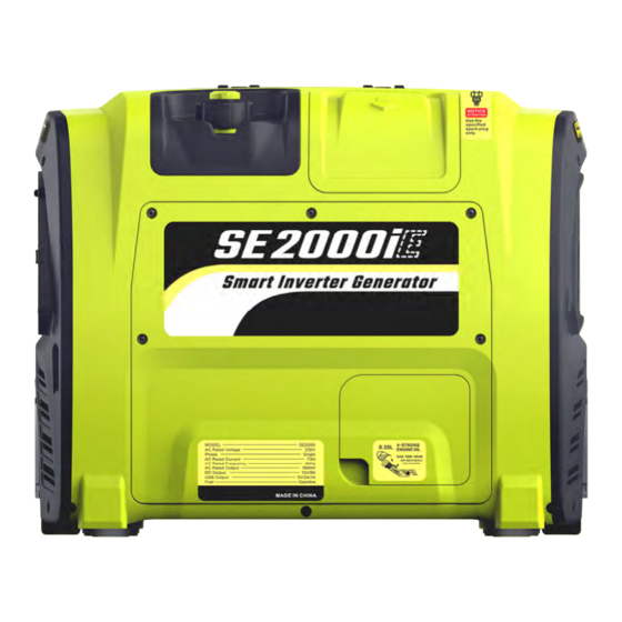
Page 64: Specifications
13. SPECIFICATIONS SE 2000i(E) SPECIFICATIONS DIMENSIONS AND WEIGHT Overall Length 530mm (20.9 in) Overall Width 320mm (12.6 in) Overall Height 430mm (16.9 in) Dry Weight 24kg / 26kg (53lbs /57lbs) ENGINE Type 4-stroke gasoline OHV Cooling System Forced air Cylinder Arrangement Inclined, single cylinder Displacement 80cm... - Page 65 Safety Device Type DC Protector NOTE (1). SE2000i is equipped with recoil starter, and SE2000iE with recoil starter & electric starter. (2). The rated and maximum output power of the generator is based on resistive load, and is not applicable to inductive load and capacitive load.
-
Page 66: Wiring Diagram
14. WIRING DIAGRAM ‐ 65 ‐ ... - Page 67 ‐ 66 ‐ ...
-
Page 68: Environment Correction
15. ENVIRONMENT CORRECTION Generating sets may only be loaded up to their rated power under the rated ambient conditions. If generating set use is under conditions which do not conform to the reference conditions as stipulated in this part of ISO 8528 and if cooling of the engine or alternator is impaired, e.g. - Page 69 More power More portable EASY POWER WITH YOU ...
Need help?
Do you have a question about the SE2000i and is the answer not in the manual?
Questions and answers