Table of Contents
Advertisement
Quick Links
Advertisement
Table of Contents

Related Manuals for Siqura S-54 E-MC


Summary of Contents for Siqura S-54 E-MC
- Page 1 S-54 E-MC Firmware Version 3.10 4-channel multicodec video server...
- Page 2 Any brand names mentioned in this manual are registered trademarks of their respective owners. Liability Siqura accepts no liability for claims from third parties arising from improper use other than that stated in this manual. Although considerable care has been taken to ensure a correct and suitably comprehensive description of all relevant product components, this manual may nonetheless contain errors and inaccuracies.
-
Page 3: Table Of Contents
Contents About This Manual ..................Safety and compliance information ............Safety information ................Declaration of Conformity ..............Product Description ................... Product Overview ................Front Panel ..................Installation ....................Powering the Unit ................Connecting Cables ................Startup ....................Connector Pin Assignments ..............Updating Device Definitions .............. - Page 4 Contents 10.4.2.1 Notes ..................10.4.2.2 Making a Video Connection ............10.4.2.3 Advanced Settings ..............10.4.2.4 Meta data insertion ..............10.4.2.5 Notes ..................10.4.3 Live View tab .................. 10.4.3.1 Advanced Settings ..............10.4.4 OSD tab ..................10.4.4.1 Text tab ................... 10.4.4.2 Graphics tab ................10.4.5 VMD tab ..................
- Page 5 Contents Appendix: Video Player Plug-In Installation ..........13.1 QuickTime ..................13.2 VLC ....................
-
Page 6: About This Manual
This manual is aimed at network engineers, technicians, and operators involved in the installation and operation of network devices, such as the S-54 E-MC. Assumed skills and know-how To work with a S-54 E-MC unit, a technician or operator must have adequate knowledge and skills in the fields of: ●... -
Page 7: Safety And Compliance Information
Failure to comply with any precaution, warning, or instruction noted in the manual is in violation of the standards of design, manufacture, and intended use of the module. Siqura assumes no liability for the customer's failure to comply with any of these safety requirements. - Page 8 Safety and compliance information Optical Safety (S-54 E-MC /SFP) This optical equipment contains Class 1M lasers or LEDs and has been designed and tested to meet IEC 60825-1:1993+A1+A2 and IEC 60825-2:2004 safety class 1M requirements. Warning: Optical equipment presents potential hazards to testing and servicing personnel, owing to high levels of optical radiation.
-
Page 9: Declaration Of Conformity
Safety and compliance information Care and Maintenance The encoder will normally need no maintenance. In order to keep the module operating reliably, please observe the following. ● Prevent dust from collecting on the module. ● Do not expose the equipment to moisture. ●... -
Page 10: Product Description
S-54 E-MC offers an independent bidirectional data channel. Models The S-54 E-MC can be housed in an MC 10 or MC 11 power supply cabinet, but is also available as a stand-alone module (/SA version). The S-54 E-MC is optionally available with a pluggable SFP slot for connections via a fiber optic cable (/SFP). -
Page 11: Front Panel
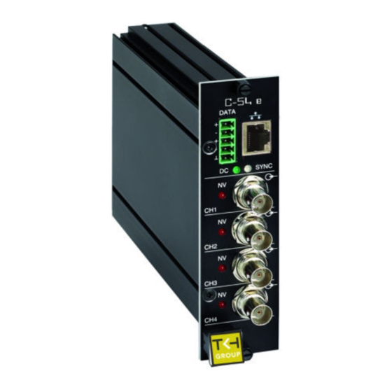
FTP Push On the occurrence of an event the S-54 E-MC can post a JPG image on a remote server. The unit pushes the image to one or two FTP servers. The event can be triggered externally, by VMD, the Image Quality Monitor, Tampering Detector, etc., or the S-54 E-MC can periodically... - Page 12 Ethern green/yellow Green on/off: 100/10 Mbit Yellow on/blink: link OK, socket active s LEDs Yellow off/flash: link down, TX attempt S-54 E-MC front panel features and indications For pin assignments, see Connector Pin Assignments ( on page 14).
-
Page 13: Installation
Installation This chapter describes how to install your S-54 E-MC unit and connect power, network, and signal cables. In This Chapter 4.1 Powering the Unit....................13 4.2 Connecting Cables....................13 4.3 Startup........................14 4.4 Connector Pin Assignments..................14 4.5 Updating Device Definitions..................15... -
Page 14: Startup
Connector Pin Assignments Mini Combicon connector pin assignments Correctly connecting the + and - inputs and outputs on the S-54 E-MC's green mini Combicon connector to the inputs and outputs on other equipment such as cameras, for example, requires special attention! Warning: Do not reverse the wires. -
Page 15: Updating Device Definitions
Installation Updating Device Definitions If the S-54 E-MC is not supported by the TKH Security application software on your host PC you can download EMX updates and MX Plug-in updates at www.tkhsecurity.com/support- files. Install the EMX update first if you are performing both update types. -
Page 16: Connections
5.1 Establishing a Network Connection................16 5.2 Making Video and Data Connections................ 17 Establishing a Network Connection The factory-set IP address of the S-54 E-MC is in the 10.x.x.x range. You will find it printed on a sticker on the unit. S-54 E-MC product sticker Note: This is the address the unit will revert to if you issue a Reset to factory settings;... -
Page 17: Making Video And Data Connections
Changing host PC IP settings to the factory-default settings of the unit At this point, connect your PC to the S-54 E-MC. You can connect them directly using a crossover cable, or connect both to a switch. Step 2: Accessing the unit Using a standard web browser you can now log on to the S-54 E-MC's internal web server. - Page 18 Connections Streams and connectors Each signal stream transmitted and received by the S-54 E-MC (see the figure below) can be conceived of as using virtual connectors (transmitters and receivers) on the network side. Each of the unit's virtual connectors has a name; through the internal web pages, the receivers can be assigned a port number that must be used only once for that particular device.
- Page 19 Connections For more information on port numbers, see Port Numbers ( on page 107).
-
Page 20: Interfaces
HTTP API specification at www.tkhsecurity.com/support-files. Web User Interface Using the S-54 E-MC's internal web server is the most straightforward way to access the unit. The S-54 E-MC's web pages enable you to configure the unit's settings and view live video images from a standard web browser, eliminating the need for a separate application program. -
Page 21: Snmp
The Simple Network Management Protocol (SNMP), part of the internet protocol suite, can be used to monitor network devices such as the S-54 E-MC for conditions or events that require administrative attention. For more details, refer to appropriate literature on SNMP. -
Page 22: Media Streaming Via Rtsp
Media Streaming via RTSP The easiest way to extract a video stream from the S-54 E-MC is to use the Real-Time Streaming Protocol (RTSP). This chapter explains the role of the S-54 E-MC in RTSP media sessions and describes how to open a video stream from the S-54 E-MC in a video player plug-in. -
Page 23: Transfer Via Udp Or Tcp
S-54 E-MC video stream viewed in QuickTime Transfer via UDP or TCP The S-54 E-MC reports to the client that it supports transfer over UDP and TCP. The choice is made on the client side. In VLC, for example, using a TCP connection can be forced (Preferences >... -
Page 24: Accessing The Internal Web Server
Accessing the Internal Web Server The web pages of the S-54 E-MC offer a user-friendly interface for configuring the unit's settings and viewing live video images over the network. This chapter explains how to connect to the S-54 E-MC's built-in web server. - Page 25 Accessing the Internal Web Server S-54 E-MC login page Connect box...
-
Page 26: Web
Using the menu on the left of each web page you can navigate to the other web pages. The first option in the menu is the home page of the S-54 E-MC. The pages listed below the home page enable you to view and configure the device settings of the unit. - Page 27 Advanced >>. Click << Simplified to hide the Advanced Settings. Important: Please be aware that configuring advanced settings requires in-depth understanding of the impact of your changes on the workings of your S-54 E-MC unit. If in doubt, do not change the default values.
-
Page 28: Working With The Web
A standard web browser on a desktop or laptop PC with a connection to your video network is all it takes to view live video encoded and streamed by the S-54 E-MC. Working with the web pages you can also control a connected PTZ camera, configure the S-54 E-MC's device settings, and remotely upgrade the embedded software. -
Page 29: Matrix Mode
Working with the Web Pages Home page After a successful login, the home page of the S-54 E-MC displays. On this page, named Live Video, you can view live images from the video source(s) connected to the unit. The Live View function is inactive when the page opens. -
Page 30: Maximized Mode
The video player plug-in used for the previews on this page and the Video page. No Player The S-54 E-MC supports QuickTime and VLC. If neither is detected on the host machine the Video player list has a “No Player” indication. For more information, refer to Appendix: Video Player Plug-In Installation. -
Page 31: Ptz Camera Control Via Your Browser
If the selected driver is supported by the PTZ camera connected to the S-54 E-MC, you can use the panel to control the camera and manage the camera's presets. PTZ drivers not included in the driver list on the PTZ page can be uploaded to the S-54 E-MC via PTZ Driver Management on the same page. - Page 32 Working with the Web Pages PTZ control panel The Preset section is designed for working with preset camera positions. To enter and save a preset camera position Click the appropriate number button(s) to enter the preset number. Adjust the position of the camera for the desired view. When satisfied with the position, click SET.
-
Page 33: Status
Working with the Web Pages 10.2 Status Status page: a snapshot with automatic page updating The Status page has two tabs: Status and Measurements. 10.2.1 Status tab The Status tab provides information on the stream states of video streams. A stream state is reported as Idle, Waiting, or OK. -
Page 34: Measurements Tab
Working with the Web Pages 10.2.2 Measurements tab Status page, Measurements tab: a snapshot with automatic page updating Measurements The Measurements tab shows module temperatures (current and peak), module uptime, network specifics, such as the MAC address and the actual IP address, the network load from this module, the load information per processor, and signal stream-specific details. -
Page 35: Advanced Settings
On the Network page, you can set the unit's IP address, subnet mask and gateway IP address. For correct functioning of the S-54 E-MC, it is vital to set its network addressing to be compatible with the subnet it is hooked into. -
Page 36: Video
It is also possible to use the Session Announcement Protocol (SAP) to transmit video streams to multicast destinations. Per channel, the S-54 E-MC also has a Live View Encoder that can convert the analog video input signal to MJPEG format for streaming to web applications or remote devices using HTTP... -
Page 37: General Tab
Working with the Web Pages 10.4.1 General tab Video 1 page: General tab with Show Preview button pressed Settings on the General tab apply to all encoders. - Page 38 Audio Disabled Visible in Encoder 1 and 2 mode. S-54 E-MC does not feature audio. Contrast Move the slider or type a value to adjust the setting aided by the visual feedback from the preview.
-
Page 39: Encoder # Tab
Working with the Web Pages Encoder Priorities Priority list Each priority on the Encoder Priority list can be assigned once. The encoder with High (1) priority consumes all CPU power it needs, leaving the remainder, if any, to the next in line. The encoder with Medium (2) priority will show the same behavior, possibly leaving little or no CPU power to the Low (3) priority encoder. - Page 40 Encoding mode MPEG-4, MPEG-2, or The method used to compress the analog MJPEG video input signal. The S-54 E-MC can stream (M)JPEG over UDP and HTTP. ● To enable and configure UDP/MJPEG streaming, select MJPEG from the Encoding mode list and configure settings.
- Page 41 In addition, VGA (640x480) and QVGA (320x240) are also supported. For more information on CIF resolutions, see Notes ( on page 42). Note: Per video input, the S-54 E-MC will simultaneously handle dual MPEG-2/4 encoding at full frame rate (MPEG-2 in I-frame only), and Live View encoding at 5 frames per second.
-
Page 42: Notes
Closes the preview. This may improve webpage responsiveness. Audio disabled Visible in Encoder 1 and 2 mode. S-54 E-MC does not feature audio. Combinations of settings Set sensible combinations of video bit rate mode, resolution, GOP length, and frame and bit rates. - Page 43 Working with the Web Pages ● configuring the decoder's settings To configure the encoder's settings Open the encoder's web pages, go to the Video page, and select the appropriate Encoder tab. In the Transmitter Settings section, specify the destination IP address. This is the address of the video decoder that will be receiving the video stream.
-
Page 44: Advanced Settings
Working with the Web Pages 10.4.2.3 Advanced Settings Important: If in doubt about these settings, do not change the default values. Encoder Advanced Settings, Encoder, MPEG-2 mode Encoder (MPEG-2 mode) Frame rate divider Relates to the frame rate configured in the Encoder Settings section. - Page 45 Working with the Web Pages Encoder Advanced Settings, Encoder, MPEG-4 mode (Variable bit rate) Encoder (MPEG-4 mode) VBR maximum Range: [0...15000]. Sets a limit for variable bit rate. bit rate Q min I Used to achieve consistent picture quality within a single GOP or across consecutive GOPs.
- Page 46 Working with the Web Pages Encoder Advanced Settings, Encoder, MJPEG mode (Constant quality) Encoder (MJPEG mode) VBR maximum bit Range: [0...15000]. Sets a limit for variable bit rate. rate Frame rate divider Relates to the frame rate configured in the Encoder Settings section.
- Page 47 Working with the Web Pages Stream Manager Stream bandwidth Range: [0...100000] kbit/s. Sets the maximum bit rate per stream limit sent to the transmitters. This will serve to spread bursts but in its turn may give rise to latency, e.g. when handling large I-frames. You are advised to limit the outgoing bit rate per encoder to a maximum of 15Mbit/s.
- Page 48 Working with the Web Pages Transmitter # DSCP field Range: [0...63]. DSCP (Differentiated Services Code Point) uses the first 6 bits of the ToS (Type of Service) field in the header of IP packets for packet classification purposes. The bit pattern in the field indicates the type of service and forwarding behavior at the next node.
- Page 49 The S-54 E-MC includes a SAP announcer. The Session Announcement Protocol is used to advertise that a media stream generated by the S-54 E-MC is available at a specific multicast address and port. The S-54 E-MC can send SAP multicast streams for Encoder 1 and Encoder...
- Page 50 Working with the Web Pages SAP Settings Enable SAP When selected, session announcements are sent at the frequency determined by the Announcement interval parameter and the media stream is transmitted to the multicast IP address specified in the Stream dest. IP address box. Stream name Enter a descriptive name to identify the media stream.
-
Page 51: Meta Data Insertion
Meta data insertion Enabling All S-54 E-MC encoders can be configured to include meta data in the video streams they generate. The insertion of meta data is enabled by setting an interval via the Advanced Settings of the encoder. A meta data message is added to the stream as a block of data with a fixed format (see examples below). - Page 52 Working with the Web Pages Prod. Serial Softw. 0x00 name 0x80 number version 0x80 (ASCII) (ASCII) (ASCII) For MPEG-2 and MPEG-4, Meta Data is preceded by the Meta Data header (00 00 01 B2): 0x00 0x00 0x01 0xB2 Meta Data message For MJPEG, these (for the rest identical) messages will be inserted as comment field (FF FE): Size 0xFF...
- Page 53 Working with the Web Pages Status 1 Video status Bit 0 (lsb) Video loss on input Bit 1 Black/white video Bit 2 VMD alarm Bit 3 Tampering alarm Bit 4 Image quality alarm Bit 5 (for future use, will be ‘0’) Bit 6 (for future use, will be ‘0’) Bit 7 (msb)
-
Page 54: Notes
Working with the Web Pages 10.4.2.5 Notes Note on Differentiated Services: Differentiated Services (DiffServ, or DS) is a method for adding QoS (Quality of Service) to IP networks. In routed networks, critical network traffic such as video and audio streams, which require a relatively uninterrupted flow of data, can get blocked due to other traffic. - Page 55 Working with the Web Pages Stream Manager and FloodGuard...
-
Page 56: Live View Tab
Live View tab Video page, Live View tab (M)JPEG output S-54 E-MC provides multiple (M)JPEG output methods. ● To transport JPEG over HTTP and/or to use the Live View previews in the web pages, enable the Live View encoder and configure its settings. -
Page 57: Advanced Settings
Resolution Set sensible combinations of mode, resolution, frame rate and (maximum) bit rate. It is advised to limit MJPEG encoding to 5 fps when the S-54 E-MC Frame rate is also handling MPEG-2/4 encoding with 1xD1 and 1xCIF or 2CIF at full (Maximum) frame rate. -
Page 58: Osd Tab
Video 1 page, OSD tab OSD facilities The S-54 E-MC features programmable on-screen display (OSD) facilities. One graphic and up to three OSD text bars can be displayed, each of which can be independently configured. Visual feedback is provided in the preview. -
Page 59: Text Tab
Working with the Web Pages Item Description Enable All OSD objects can be enabled and configured separately. To (temporarily) remove a bar or graphic from the screen, clear the Enable check box. OSD text The text to be displayed. Maximum: 255 characters. Text is displayed in a single line. - Page 60 Working with the Web Pages Text # tab Text color Changes made here and in the other fields are immediately written into the device and reflected in the preview. Border/outline color Font size Range: [0...256]. Predefined positions Presets for positioning the OSD object. Transparency Move the slider or type a percentage.
-
Page 61: Graphics Tab
Working with the Web Pages For OSD texts, you can use the S-54 E-MC's default fonts or fonts you upload to the unit. To upload a font In the Font management section, click Browse. The Open dialog box displays. Browse to the folder containing the font to be uploaded. - Page 62 Working with the Web Pages Graphics tab Predefined positions Presets for positioning the OSD object. Transparency Move the slider or type a percentage. X-Position Variables that enable you to freely position the object, instead of using the presets. Drag the sliding buttons or enter a percentage. Y-Position When a preset has been selected, changing one of its defined parameters sets the Predefined positions box to ‘--’, indicating that...
-
Page 63: Vmd Tab
Working with the Web Pages The file appears in the File textbox. To start the upload, click Add. The graphic is added to the graphics list and to the Graphic drop-down list in the Text section.To remove a graphic In the Graphic Management section, select the graphic. Click Del. -
Page 64: Vmd Configuration 1: Detection Parameters
Working with the Web Pages 10.4.5.2 VMD Configuration 1: Detection Parameters VMD enabled: Configuration section with controls, video picture, and motion detection inset, the latter with mask applied. The mask permits motion detection in the right half of the picture only, at the top of the stairs, so passers-by and cars would not be registered by the detector facility;... - Page 65 Working with the Web Pages Use the 'Save' button to store the mask in the unit. To delete a mask ● Press the Clear button. Masking grid Configuration Brush Normal Allows grid elements to be accessed in 4- element groups. Large Allows grid elements to be accessed in 16- element groups.
-
Page 66: Vmd Detection Window
Working with the Web Pages 10.4.5.4 VMD detection window The VMD detection window shows up as a small picture within the larger picture. Depending on the thresholds set, the motion detection bar on the right side of the picture shows up green or red (see figures below), the latter indicating a VMD alarm will be generated. - Page 67 Working with the Web Pages Frame rate divider Range: [1...100]. Used to determine the number of frames used for VMD. Only 1 divided by this value frames are evaluated. Delay Range: [1...10] frames. The delay in frames between the currently processed frame and the stored frame with which it is to be compared.
- Page 68 Working with the Web Pages VMD Alarm: Event window high/low mark X = Event window size Y = Event window high mark Z = Event window low mark VMD alarm becomes active when in at least Y out of X frames motion is detected. VMD alarm becomes inactive when in at least Z out of X frames no motion is detected.
-
Page 69: Ftp Push Tab
Video 1 page, FTP Push tab JPEG image posting The S-54 E-MC can be configured to upload images, generated by its Live View encoder, to an FTP server. Posting the files in JPEG format can be set to be continuous or event-triggered. On... - Page 70 $_@.jpg". State>.jpg FTP server A target FTP server must hold a user account associated with the S-54 E-MC. You can assign a primary server and a secondary server. Images are posted simultaneously to both the primary server and secondary server.
- Page 71 Working with the Web Pages Primary/Secondary Server Enable Select or clear to respectively enable/disable the connection with this server. IP address IP address of the FTP server. Port The FTP protocol typically uses port 21 on the FTP server to listen for clients initiating a connection.
-
Page 72: Image Quality Tab
Working with the Web Pages Last post status: example of error message 10.4.7 Image Quality tab Video 1 page: Image Quality tab Image Quality Monitor The Image Quality Monitor can detect if images produced by a camera connected to a S-54 E- MC video input are still usable. -
Page 73: Enabling The Image Quality Monitor
Working with the Web Pages ● The iris control has got stuck. ● Camera failure. 10.4.7.1 Enabling the Image Quality Monitor The Image Quality Monitor can measure camera focus, exposure, contrast level, and SNR (Signal-to-Noise Ratio). The four measurements are disabled by default (see the figure above). -
Page 74: Dial Legend
Working with the Web Pages Image Quality: FOCUS measurement enabled only 10.4.7.2 Dial legend The colored dials in the Measurements section provide a quick and easy glance at the health of the camera. You can fine-tune each measurement's alarm thresholds to your needs in the VCA Settings section. - Page 75 Working with the Web Pages Hysteresis and alarm output The Measurement rises above the trip point. After expiry of the delay set for the Min. event duration, the alarm is activated. The Measurement drops into the Hysteresis area (i.e. the margin between incorrect and correct performance) but falls short of the "safe"...
-
Page 76: Measurements Configuration
Note: In addition to the visual indications on the web pages, alarms can also be read from the S-54 E-MC 's internal Management Information Base (MIB) using appropriate software. 10.4.7.3 Measurements configuration Image Quality: VCA Settings The default Measurements values will mostly work well for you. - Page 77 Working with the Web Pages VCA Settings Configure Alarms Min. event duration Alarm output delay time: the time span that is to elapse before a continued change in conditions actually activates/deactivates the alarm output. Alarm output True or False. Indication of current status. Configure Focus Allow you to enable/disable each measurement separately and Measurement...
-
Page 78: Region Of Interest (Roi)
Working with the Web Pages 10.4.7.4 Region of Interest (ROI) Region of Interest (ROI) Pressing the Show ROI>> button in the ROI Settings section opens a preview with a grid overlay. You can use it to mask portions of the image you wish to exclude from monitoring. Certain regions can disrupt the measurements or be of no importance. -
Page 79: Tampering Detector Tab
Working with the Web Pages Configuration Brush Normal Allows grid elements to be accessed in 4- element groups. Large Allows grid elements to be accessed in 16- element groups. Small Allows grid elements to be accessed one at a time. Invert Mask Enables you, for example, to start creating a mask by marking the (smaller) area(s) you do wish to monitor and then use this button to... -
Page 80: Enabling The Tampering Detector
As a result of tampering, or more accidentally, after cleaning, a camera may no longer cover the area designated for monitoring. The S-54 E-MC's Tampering Detector function can detect camera position changes and scene changes such as a blocked camera view, for example. It does so by comparing the current image to one or more reference images that were captured and stored earlier. - Page 81 Working with the Web Pages This parameter enables you to capture the background of a scene only and have specific elements such as moving objects filtered out of the image. With a longer time span for the sampling duration, persons passing in front of the camera, for example, or cars driving on a highway can be smoothed out to prevent them from triggering a changed scene alarm.
- Page 82 Working with the Web Pages Current image matches Reference 1 Reference image(s) available. No match found with current image, though. The drop-down list in the Feedback View section can be used to display the current image, the best matching reference image, or a specific reference image. Feedback view list To delete a reference image In the VCA Settings section, open the Reference image list.
-
Page 83: Position Measurement
Working with the Web Pages 10.4.8.3 Position measurement Position Measurement settings After creating one or more reference images you can configure the Position Measurement settings to define thresholds for allowed camera movement and image matching. Configure Position Measurement Enable Select or clear to enable or disable the Tampering Detection functionality, respectively. - Page 84 Note: In addition to the status indication in this section, alarms can also be read from the S-54 E-MC 's internal Management Information Base (MIB) using appropriate software. Configure Alarms Min.
-
Page 85: Data Rs-422/485
Working with the Web Pages Camera has moved further to the right. Current Blocked scene alarm image no longer matches any reference image, resulting in a changed scene alarm. 10.5 Data RS-422/485 Data RS-422/485 page. Transmitter and receiver can be configured in the usual manner. - Page 86 UART Settings. Right: selectable speeds. UART The S-54 E-MC uses a Universal Asynchronous Transmitter/Receiver (UART) for data transmission. The UART will recognize and reproduce the words in the data stream. This is only possible if the UART is programmed to understand the serial data format.
- Page 87 Working with the Web Pages Making data connections MX Transmitter/Receiver Settings After selecting a data mode (see General Settings) and configuring the interface (see UART Settings), data link configuration is done in the same fashion as described for video links. To configure a data link In the Transmitter settings section, set at least one destination IP address.
-
Page 88: Advanced Settings
Working with the Web Pages TCP Server Settings Server enable Enables streaming of UART data over TCP using a client/server connection. The server accepts requests from a specific client, or any host if not specified. Server port Range: [0...65535]. 10.5.1 Advanced Settings RS-4xx Settings Advanced Settings, RS-4xx... - Page 89 Working with the Web Pages Note on Data Transfer Optimisation: A 'word time' is the transmit time for one data word. The amount of time one data word takes to travel on the line is determined by bit rate and word length. Using the UART gap timeout and UART max. latency variables you can tailor the data channel for your specific protocol.
- Page 90 Working with the Web Pages Receiver # Advanced Settings, Receiver 1 Receiver # Source port filter Can be used to filter incoming data traffic. With multiple signals sent to the same IP address and destination port number, Source port filter can be used to filter the input, that is - to accept only data from the transmitting port specified here.
-
Page 91: Ptz
10.6.1 Enabling PTZ camera control A PTZ camera connected to the S-54 E-MC can be controlled with the PTZ Control Panel on the Live Video page. PTZ camera control is enabled by selecting a driver that is supported by the camera. If the required driver is not included in the PTZ driver list, you can upload it to the S-54 E-MC (see below). -
Page 92: Uploading/Removing Ptz Drivers
Working with the Web Pages 10.6.2 Uploading/Removing PTZ drivers To upload a PTZ driver In the PTZ Driver Management section, click Browse. The Open dialog displays. Browse to the folder containing the driver. Select the appropriate file (.txt or .js extension), and then click Open. The driver displays in the File text box. -
Page 93: Event Management
Working with the Web Pages 10.7 Event Management Event Management page Associating events with FTP Push If FTP push is configured to be event-triggered, you need to select one or more sources on the Event Management page that will activate an image upload to the FTP server(s). FTP Push # Available inputs List of sources that can be selected as triggers for an FTP push. -
Page 94: Device Management
Working with the Web Pages 10.8 Device Management Device Management page, General tab 10.8.1 General tab Identification This section offers administrative module information. Device name Label 1 The Device name section contains label settings, which can be edited and saved. Values entered for the Label 1 and Label 2 Label 2 variables are stored in the Management Information Base (MIB) of the module. -
Page 95: Snmp Tab
Device Management page, SNMP tab SNMP MIB To prepare a S-54 E-MC for SNMP management, the database documenting the S-54 E-MC variables that can be read or modified must be registered with the program; such SNMP MIB documents (indicated OPTC) are available from TKH Security or from its website. -
Page 96: Mx Tab
Working with the Web Pages SNMP Traps A S-54 E-MC alarm status change will generate a trap which can be caught by any SNMP manager. Version and Destination IP : port are required fields. SNMP Traps Version The SNMP version used. -
Page 97: Auto Discovery Tab
On the Auto Discovery tab you can enable UPnP (Universal Plug and Play). If enabled, UPnP will allow the S-54 E-MC to advertise its presence and services to control points on the network. A control point can be a network device with embedded UPnP, a VMS application or a spy software tool (for example, Device Spy). - Page 98 Testing the S-54 E-MC's UPnP functionality After enabling UPnP, you can use a tool, such as Device Spy (included in the 'Developer Tools for UPnP Technologies'), to check if the S-54 E-MC correctly advertizes its presence and device description on the network.
-
Page 99: Firmware Tab
Start Device Spy. In the right-hand panel, double-click the Presentation URL entry. -or- In the left-hand panel, right-click the S-54 E-MC entry, and then select Display Presentation Page. The login page of the S-54 E-MC displays in your browser. Note: Do not double-click the Base URL entry in the Details pane. The connection will not be made, due to an incorrect port number. - Page 100 The upgrade image area is usually empty upon factory release. If the existing firmware in the S-54 E-MC is to be replaced, a new version can be written to the upgrade image area. There, the new image resides in erasable (flash) memory.
-
Page 101: Reboot Tab
(temporarily) moving a PC to the same subnet as the S-54 E-MC. 10.9 User Management User Management page, Web Access Tabs The User Management page is available to users with an Admin account. -
Page 102: Web Access Tab
Administrators, Operators, and Viewers. Do not use the name of one of these groups as a user name. Out of the box, the unit has no user accounts configured. The S-54 E-MC supports up to 20 users at a time. -
Page 103: Linux Tab
Working with the Web Pages Editing a user To delete a user On the User Management page, open the Web Access tab. Select the user name from the User List, and then click Remove. To confirm the deletion, press OK. 10.9.2 Linux tab User Management page, Linux tab... -
Page 104: Date And Time
The on‑screen position and colour of the text are governed by the relevant OSD settings. The S-54 E-MC adds 1 hour to the local time when Daylight Savings Time is enabled. The unit does not automatically change between summer and winter time. The user has to set the proper state in the Date and Time section of the web page (or use an MX/IP command). -
Page 105: Advanced Settings
Working with the Web Pages ● You should never test the tracking to the time server by changing the time in the NTP server. You can only test it by leaving Time Service mode, changing “Local Time” slightly (max 5 minutes), and then enabling Time Service mode again. ●... -
Page 106: Multicasting, Multi-Unicasting, And Port Numbers
UDP streams used. Multicast group A multicast group is used by the source, that is - the S-54 E-MC, and the receivers to send and receive multicast messages. To define a multicast group, the source unit should be assigned a valid multicasting ('destination') TX stream address and the destination units should get this same address as source. -
Page 107: Multi-Unicasting
11.2 Multi-Unicasting As an alternative to multicasting, the S-54 E-MC features 'multi-unicasting', that is - sending out up to 4x2x3 independent copies of video, and sending and receiving four data streams. If the bit rates selected are moderate, it may be more convenient to use this mechanism instead of multicasting, even though the network gets more signal to carry from the encoder. - Page 108 Multicasting, Multi-Unicasting, and Port Numbers General Example Video 50xxx Video 50010 Audio 51xxx Audio 51010 Data 52xxx Data 1 52010 (RS-4xx) Data 2 52020 (RS-232) 53xxx CC 1 53010 CC 2 53020 Default port numbers TKH Security MX applications using automatic port number allocation may use 55000 and up.
-
Page 109: Appendix: Enabling Javascript
Appendix: Enabling JavaScript In order for the S-54 E-MC web pages to display correctly, JavaScript must be enabled in your web browser. To enable JavaScript in Internet Explorer From Internet Explorer's Tools menu, select Internet Options. On the Security tab, click the Internet globe icon, and then click Custom level. - Page 110 Appendix: Video Player Plug-In Installation Viewing video streams on the S-54 E-MC web pages requires a video player installation on the machine running the web browser. This appendix provides instructions for installing QuickTime and VLC, the video plug-ins supported by the S-54 E-MC.
- Page 111 Appendix: Video Player Plug-In Installation Required components: Mozilla and ActiveX plug-ins Warning: Do not use VLC v0.8.6f. This version will stop running after 30 seconds. The S-54 E-MC has been successfully tested with VLC v2.0 or higher VLC and Windows Vista To configure VLC media player settings when running this plug-in on a Windows Vista PC.
Need help?
Do you have a question about the S-54 E-MC and is the answer not in the manual?
Questions and answers