Advertisement
Quick Links
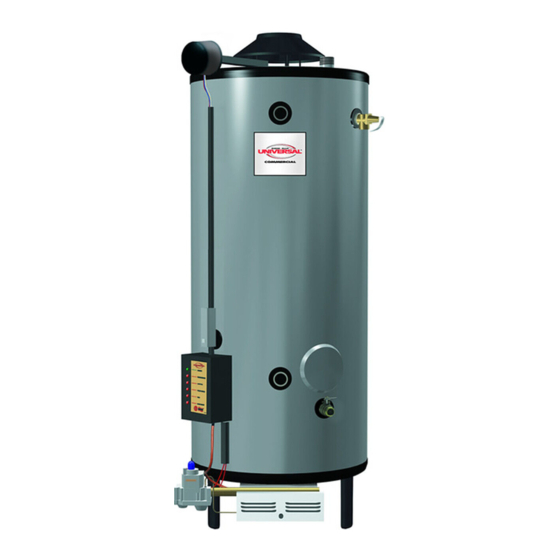
Commercial Induced Draft Water Heater
USE & CARE MANUAL
WITH INSTALLATION INSTRUCTIONS FOR THE CONTRACTOR
®
CERTIFIED
R
!
Recognize this symbol as an Indication of Important
Safety Information!
NOTICE: This water heater is designed for use in a commercial application and the installation and maintenance of it should be per-
!
formed by a qualified, licensed service personnel. If the foregoing assumption is not appropriate, then we recommend that you obtain
and retain our Residential Use & Care Manual which contains additional consumer warnings and information.
!
CALIFORNIA PROPOSITION 65 WARNING: This product contains chemicals known to the State of California to cause cancer, birth
defects or other reproductive harm.
WARNING: If the information in these instructions are not followed exactly, a fire or explosion may result
!
causing property damage, personal injury or death.
!
FOR YOUR SAFETY!
— Do not store or use gasoline or other flammable
vapors or liquids or other combustible materials in
the vicinity of this or any other appliance. To do so
may result in an explosion or fire.
— WHAT TO DO IF YOU SMELL GAS
•
Do not try to light any appliance.
•
Do not touch any electrical switch; do not use any
phone in your building.
Printed in USA
MULTI-FLUE COMMERCIAL MODELS
!
•
Immediately call your gas supplier from a neigh-
bor's phone. Follow the gas supplier's instructions.
•
If you cannot reach your gas supplier, call the fire
department.
•
Do not return to your building until authorized by
the gas supplier or fire department.
— Improper installation, adjustment, alteration, service
or maintenance can cause injury, property damage
or death. Refer to this manual. Installation and ser-
vice must be performed by a qualified installer, ser-
vice agency or the gas supplier.
Do Not Destroy this Manual. Please read carefully and
keep in a safe place for Future Reference.
AP13968 (06/06)
Advertisement

Related Manuals for Rheem Universal GD100-250


Summary of Contents for Rheem Universal GD100-250
- Page 1 Commercial Induced Draft Water Heater USE & CARE MANUAL WITH INSTALLATION INSTRUCTIONS FOR THE CONTRACTOR MULTI-FLUE COMMERCIAL MODELS ® CERTIFIED Recognize this symbol as an Indication of Important Do Not Destroy this Manual. Please read carefully and Safety Information! keep in a safe place for Future Reference. NOTICE: This water heater is designed for use in a commercial application and the installation and maintenance of it should be per- formed by a qualified, licensed service personnel.
- Page 2 READ THE SAFETY INFORMATION TABLE OF CONTENTS Your safety and the safety of others are very impor- tant. There are many important safety messages in Safety Information this manual and on your appliance. Always read and obey all safety messages. Safety Precautions .
- Page 3 General Safety Precautions To meet commercial water use needs, the thermostat on this water The following chart details the relationship of water temperature heater is adjustable up to 180°F. However, water temperatures over and time with regard to scald injury and may be used as a guide in 125°F.
- Page 4 General Safety Precautions Be sure to read and understand the entire Use & Care Manual before attempting to install or operate this water heater. Pay particular attention to the following General Safety Precautions. Failure to follow these warnings could result in a fire or explosion, causing prop- erty damage, bodily injury or death .
- Page 5 Introduction D D . . R R E E S S T T A A U U R R A A N N T T S S — — If the water heater is to be installed in a restau- rant or other location where the floor is frequently cleaned, it must be elevated to provide at least six inches (15 cm) of clearance Read and Review this entire Manual with special emphasis on...
- Page 6 Installation contain such hydrocarbons. The air there may be safe to 3 3 . . W W A A T T E E R R C C O O N N N N E E C C T T I I O O N N S S — — This water heater may be connected breathe, but when it passes through a gas flame, corrosive individually, in multiples with others, or with an external hot water elements are released that will shorten the life of any gas burn-...
- Page 7 Installation NOTES: Discharge Pipe to Suitable Open Drain Hot Outlet 1.) Heater's Outlet Piping must have upward Storage slope, otherwise use Circulator Tank 2.) If Vertical Tank is used, follow same lay- out. Temperature & Pressure Relief Valve 3.) The gas supply piping must be adequate- (See Local Code) ly supported and aligned to minimize loads (forces) on the water heater’s gas...
- Page 8 Installation A ground joint union and manual shutoff valve should be installed 7 7 . . V V E E N N T T I I N N G G — — The responsibility for providing a vent of adequate ca- in the gas line near the water heater so that the burner assembly pacity and in good usable condition is that of the installing contrac- may be easily removed.
- Page 9 Installation ❑ A A . . W W a a t t e e r r H H e e a a t t e e r r L L o o c c a a t t i i o o n n Soap and water solution used to check all connections and fittings for possible gas leak.
- Page 10 Operation Before operating this water heater, be sure to read and follow the instructions on the label pictured below and all other labels on the water heater, as well as the warnings printed in this manual. Failure to do so can result in unsafe operation of the water heater resulting in property damage, bodily injury, or death.
- Page 11 Operation Before operating this water heater, be sure to read and follow the instructions on the label pictured below and all other labels on the water heater, as well as the warnings printed in this manual. Failure to do so can result in unsafe operation of the water heater resulting in property damage, bodily injury, or death.
- Page 12 Operation S S A A F F E E T T Y Y P P R R E E C C A A U U T T I I O O N N S S A A . . D D o o turn off manual gas shut-off valve if water heater has been sub- mops to accumulate near water heater.
- Page 13 Operation To insure accuracy for rating, clock enough cubic feet of gas so that 7 7 . . E E M M E E R R G G E E N N C C Y Y S S H H U U T T D D O O W W N N — — the clocked time is at least 60 seconds.
- Page 14 Maintenance D D . . P P R R E E S S S S U U R R E E S S W W I I T T C C H H — — Inspect the inlet to the pressure switch T T O O C C L L E E A A N N O O R R I I N N S S P P E E C C T T T T A A N N K K : : and the tubing for debris or blockage.
- Page 15 “System Sentinel” Diagnostic System The “System Sentinel” Diagnostic system on this water heater provides the user or service technician with a visual representation of the operational status of the various sections of the water heater’s control system. A quick glance at the System Sentinel panel on the front of the heater will give an indication of where to begin trouble shooting of a non operational heater.
- Page 16 “System Sentinel” Troubleshooting Guide Section 1... the “POWER” LED Is the “POWER” LED Illuminated? Is the “ON/OFF” Switch in Turn switch to ON position. Is the Power is being supplied to the “ON” position? Power LED now illuminated? the heater, the ON/OFF Switch is functioning, and the 24V AC Transformer is functioning.
- Page 17 “System Sentinel” Troubleshooting Guide Section 2... the “THERMOSTAT” LED Is the “THERMOSTAT” LED Illuminated? Thermostat is calling for heat, Ensure that power is being supplied to the water heater. Refer to “Section 1...the and 24 VAC power. POWER LED” in this Troubleshooting Guide, and correct if necessary.
- Page 18 “System Sentinel” Troubleshooting Guide Section 3... the “IGNITION” LED Is the “IGNITION” LED Illuminated? The Thermostat has called for Is Spark Ignitor operating? Is the Inducer Operating? heat, the Inducer is running, and (Can sparking be heard?) 24 VAC power is being supplied to the Ignition Control Module and the ignition sequence will begin.
- Page 19 “System Sentinel” Troubleshooting Guide Section 4... the “PILOT VALVE” LED Is the “PILOT VALVE” LED Illuminated? The Ignition Control Module is in Is the Spark Ignitor operating? the Ignition sequence, and is pro- Is the Pilot Flame burning? (Can sparking be heard?) viding 24 VAC power to the ECO (Energy Cut-Off Device) inside of the Thermostat...
- Page 20 “System Sentinel” Troubleshooting Guide Section 5... the “ECO” LED Is the “ECO” LED Illuminated? ECO is “open”. Allow tank to cool, The ECO (Energy Cut-Off device) and reset. If ECO again trips, the is not tripped (open) and power is Thermostat/High limit is defective.
- Page 21 Replacement Parts Instructions For Placing a Parts Order All parts orders should include: CAUTION: For your safety DO NOT attempt repair of gas piping, gas control (thermostat), burners, vent con- The model and serial number of the water heater from the rating nectors or other safety devices.
- Page 22 Wiring and Schematic Diagrams N N O O T T I I C C E E : : I I f f a a n n y y o o f f t t h h e e o o r r i i g g i i n n a a l l w w i i r r e e a a s s s s u u p p p p l l i i e e d d w w i i t t h h t t h h i i s s a a p p p p l l i i a a n n c c e e m m u u s s t t b b e e r r e e p p l l a a c c e e d d , , i i t t M M U U S S T T b b e e r r e e p p l l a a c c e e d d w w i i t t h h 1 1 8 8 G G A A . . , , 6 6 0 0 0 0 V V , , 1 1 0 0 5 5 ° ° C C w w i i r r e e o o r r i i t t s s e e q q u u i i v v a a l l e e n n t t , , u u n n l l e e s s s s o o t t h h e e r r w w i i s s e e n n o o t t e e d d . . CONNECTION DIAGRAM SCHEMATIC CAUTION! Label all wires prior to disconnection when servicing controls.
- Page 23 Wiring and Schematic Diagrams N N O O T T I I C C E E : : I I f f a a n n y y o o f f t t h h e e o o r r i i g g i i n n a a l l w w i i r r e e a a s s s s u u p p p p l l i i e e d d w w i i t t h h t t h h i i s s a a p p p p l l i i a a n n c c e e m m u u s s t t b b e e r r e e p p l l a a c c e e d d , , i i t t M M U U S S T T b b e e r r e e p p l l a a c c e e d d w w i i t t h h 1 1 8 8 G G A A . . , , 6 6 0 0 0 0 V V , , 1 1 0 0 5 5 ° ° C C w w i i r r e e o o r r i i t t s s e e q q u u i i v v a a l l e e n n t t , , u u n n l l e e s s s s o o t t h h e e r r w w i i s s e e n n o o t t e e d d . . CONNECTION DIAGRAM SCHEMATIC CAUTION! Label all wires prior to disconnection when servicing controls.
- Page 24 I I n n T T h h e e U U . . S S . . A A . . : : formed. Rheem Sales Co. Inc., Water Heater Division 2600 Gunter Park Drive e. Details of the problem as you can best describe them.
Need help?
Do you have a question about the Universal GD100-250 and is the answer not in the manual?
Questions and answers