Table of Contents
Advertisement
Available languages
Available languages
Quick Links
Advertisement
Table of Contents
Troubleshooting

Related Manuals for sotecc DG500

Summary of Contents for sotecc DG500
- Page 1 Einbauanleitung / Installation manual Haubenblitzer DG500/ DG1000 connectBOX & Haubenkontakt DE Seite 1-15 EN page 16-24 Version DE/EN_2.1 Herausgeber SOTECC GmbH, Armbruststr. 75, 73230 Kirchheim unter Teck Kontakt info@sotecc.de...
-
Page 2: Table Of Contents
Connect and mount canopy contact..................20 Mount canopy contact counterpart ..................21 Installation connectBOX ......................23 Wiring ............................ 23 Troubleshooting ..........................24 Function test / checking the connection to FLARM® ..............24 © 2022 SOTECC GmbH. Alle Rechte vorbehalten. Rev. 2.1... - Page 3 Einbauanleitung / Installation manual Haubenblitzer DG500/ DG1000 Contact ............................25 Anhang/Appendix ..........................26 11.1 Verkabelung mit connectBOX / Wiring with connectBOX............. 26 11.2 Verkabelung Haubenblitzer / Wiring canopyflash ..............27 © 2022 SOTECC GmbH. Alle Rechte vorbehalten. Rev. 2.1...
-
Page 4: Wichtige Informationen
Die SOTECC GmbH trägt keine Verantwortung für eigenständigen Einbau, Änderungen oder Reparaturen, Missbrauch oder Unfälle. Die SOTECC GmbH behält sich das Recht vor, Änderungen bzgl. der technischen Daten und Funktionen ohne vorherige Ankündigung vorzunehmen. SOTECC übernimmt keine Haftung bei offensichtlichen Druck- und Satzfehlern. -
Page 5: Einbauanleitung
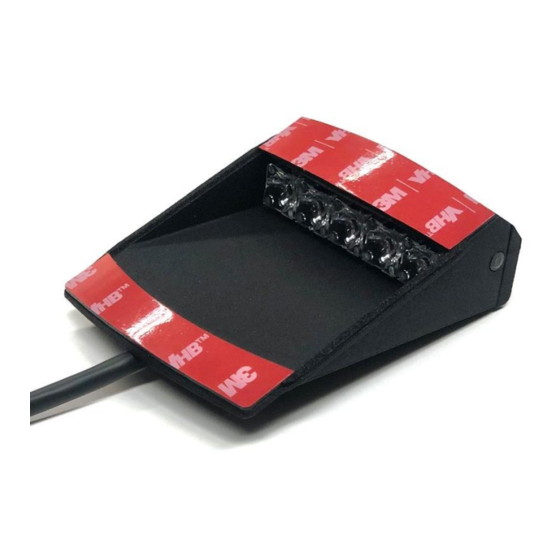
Vor Einbau die Schaumbänder auf dem Steg des Haubenblitzers auf korrekten Sitz prüfen (diese können durch den Transport verrutschen, bzw. sich ablösen). 3M- Klebestreifen zum Fixieren an der Haube auf Druckstellen prüfen. © 2022 SOTECC GmbH. Alle Rechte vorbehalten. Rev. 2.1... -
Page 6: Hinweise Zur Montage
Anschließend die Bohrschablone entfernen. Die 4 mm Bohrungen auf 6 mm erweitern und die zuvor angezeichnete Kabeldurchführung in den Haubenrahmen mit Fräser oder mehreren Bohrungen herstellen. Die M4 Gewindebuchsen in die Bohrungen mit 2 Komponenten-Kleber im Haubenrahmen fixieren. © 2022 SOTECC GmbH. Alle Rechte vorbehalten. Rev. 2.1... -
Page 7: Kabeldurchführungen Bohren
Von vorne beginnend den beigefügten Ziehdraht in den Haubenrahmen einschieben, bis dieser an der Kabeldurchführung des Haubenkontakts sichtbar wird. Den Ziehdraht und das Anschlusskabel des Haubenblitzers verbinden. Anschließend Kabel vorsichtig durchziehen. © 2022 SOTECC GmbH. Alle Rechte vorbehalten. Rev. 2.1... -
Page 8: Ankleben Des Haubenblitzers Mit Der Beigelegten Schablone
Haubenblitzer hinten leicht nach unten kippen, dass nur der vodere Klebestreifen die Haube berührt. Dann von vorne beginnend die Klebefläche vorsichtig andrücken, so dass keine Luftblasen entstehen. Abschließend alles kräftig andrücken. © 2022 SOTECC GmbH. Alle Rechte vorbehalten. Rev. 2.1... -
Page 9: Haubenkontakt Anschließen Und Montieren
Das aus dem Haubenrahmen an der Kabeldurchführung herausragende Kabel nach ca. 5cm abschneiden, abisolieren und mit dem Kabel des vorkonfektionierten Haubenkontakts verlöten. Die Kabelfarben müssen übereinstimmen. Überstehendes Kabel in den Haubenrahmen schieben und Haubenkontakt mit den zwei M4 Inbusschrauben befestigen. © 2022 SOTECC GmbH. Alle Rechte vorbehalten. Rev. 2.1... -
Page 10: Haubenkontakt Gegenstück Montieren
Lüftung aufliegend verschrauben. (siehe Zeichnung unten) Falls das Gegenstück noch nicht ganz an der richtigen Position sitzt, können kleinere Anpassungen jetzt noch am Haubenkontakt vorgenommen werden. Dafür die zwei M4 Schrauben lockern und Kontakt anpassen. © 2022 SOTECC GmbH. Alle Rechte vorbehalten. Rev. 2.1... - Page 11 Rot/plus ist in Flugrichtung vorne, oder kleinen weißen Punkt beachten, dieser auch in Flugrichtung vorne! Das Kabel durch die untere Bohrung in der Lüftung an der Bordwand entlang durch die Bohrung in der Rückenlehne führen und befestigen. Lüftungsdüse wieder verschrauben. © 2022 SOTECC GmbH. Alle Rechte vorbehalten. Rev. 2.1...
-
Page 12: Installation Connectbox
Klett anbringen. Bestenfalls so, dass alle Ports gut zugänglich sind. Haubenkontaktkabel durch die Rückenlehne führen. 2.11 Verkabeln Den 4-poligen Molex Stecker entsprechend der Skizze anschließen. Den 4-poligen Molex Stecker in den ACL-Steckplatz der connectBOX stecken. © 2022 SOTECC GmbH. Alle Rechte vorbehalten. Rev. 2.1... -
Page 13: Troubleshooting
Lösungsansatz: Bei fehlendem GPS Signal z.B. in der Halle, wird der Haubenblitzer aktiviert. Diese Funktion kann deaktiviert werden. Details dazu im Handbuch. 4 Funktionstest / Überprüfen der Verbindung zum FLARM® Dieser Abschnitt befindet sich in unserem Handbuch. © 2022 SOTECC GmbH. Alle Rechte vorbehalten. Rev. 2.1... -
Page 14: Kontakt
Einbauanleitung / Installation manual Haubenblitzer DG500/ DG1000 5 Kontakt SOTECC GmbH Armbruststrasse 75 73230 Kirchheim unter Teck E-Mail: info@sotecc.de Tel. Nr. +49 7021 9560232 © 2022 SOTECC GmbH. Alle Rechte vorbehalten. Rev. 2.1... -
Page 15: Important Information
SOTECC GmbH does not bear any responsibility for independent installation, modifications or repairs, misuse or accidents. SOTECC GmbH reserves the right to make changes to the technical data and functions without prior notice. SOTECC accepts no liability for obvious printing and typesetting errors. -
Page 16: Installation Instructions
Before installation, check the foam tapes on the bar of the canopy flasher for correct fit (these can slip or become detached during transport). Check the 3M adhesive strips for fixing to the canopy for pressure points. © 2022 SOTECC GmbH. Alle Rechte vorbehalten. Rev. 2.1... -
Page 17: Mounting
Then remove the drilling template. Extend the 4 mm holes to 6 mm and make the previously marked cable gland in the canopy frame with a cutter or several holes. Fix the M4 threaded bushes in the holes with 2 component glue in the canopy frame. © 2022 SOTECC GmbH. Alle Rechte vorbehalten. Rev. 2.1... -
Page 18: Drilling Cable Bushings
Starting from the front, push the enclosed pull wire into the canopy frame until it is visible at the cable grommet of the canopy contact. Connect the pull wire and the connection cable of the canopy flasher. Then carefully pull the cable through. © 2022 SOTECC GmbH. Alle Rechte vorbehalten. Rev. 2.1... -
Page 19: Glueing The Canopy Flasher With The Enclosed Template
Then, starting from the front, align the adhesive surfaces on the template and press on firmly so that no air bubbles form. © 2022 SOTECC GmbH. Alle Rechte vorbehalten. Rev. 2.1... -
Page 20: Connect And Mount Canopy Contact
The cable colours must match. Push the protruding cable into the canopy frame and fix the canopy contact with the two M4 Allen screws. © 2022 SOTECC GmbH. Alle Rechte vorbehalten. Rev. 2.1... -
Page 21: Mount Canopy Contact Counterpart
Red/plus is in flight direction in front, or note small white dot, this also in flight direction in front! The canopy contact must be able to move into the counterpart without jamming when closing the canopy! © 2022 SOTECC GmbH. Alle Rechte vorbehalten. Rev. 2.1... - Page 22 Haubenblitzer DG500/ DG1000 Guide the cable through the lower hole in the ventilation along the drop side through the hole in the backrest and secure it. Screw the ventilation nozzle back on. © 2022 SOTECC GmbH. Alle Rechte vorbehalten. Rev. 2.1...
-
Page 23: Installation Connectbox
Connect the 4-pin Molex connector according to the sketch. Plug the 4-pin Molex connector into the ACL slot of the connectBOX. Attach the ferrite core to the cable approx. 10cm in front of the connectBOX. © 2022 SOTECC GmbH. Alle Rechte vorbehalten. Rev. 2.1... -
Page 24: Troubleshooting
Possible solution: If there is no GPS signal, e.g. in the hall, the canopy flasher is activated. This function can be deactivated. Details in the manual. 10 Function test / checking the connection to FLARM® This section is located in our jmanual. © 2022 SOTECC GmbH. Alle Rechte vorbehalten. Rev. 2.1... -
Page 25: Contact
Einbauanleitung / Installation manual Haubenblitzer DG500/ DG1000 11 Contact SOTECC GmbH Armbruststrasse 75 73230 Kirchheim under Teck Email: info@sotecc.de Phone no. +49 7021 9560232 © 2022 SOTECC GmbH. Alle Rechte vorbehalten. Rev. 2.1... -
Page 26: Anhang/Appendix
Einbauanleitung / Installation manual Haubenblitzer DG500/ DG1000 Anhang/Appendix 11.1 Verkabelung mit connectBOX / Wiring with connectBOX © 2022 SOTECC GmbH. Alle Rechte vorbehalten. Rev. 2.1... -
Page 27: Verkabelung Haubenblitzer / Wiring Canopyflash
Einbauanleitung / Installation manual Haubenblitzer DG500/ DG1000 11.2 Verkabelung Haubenblitzer / Wiring canopyflash © 2022 SOTECC GmbH. Alle Rechte vorbehalten. Rev. 2.1...
Need help?
Do you have a question about the DG500 and is the answer not in the manual?
Questions and answers