
Summary of Contents for auer 6P10 PILOT
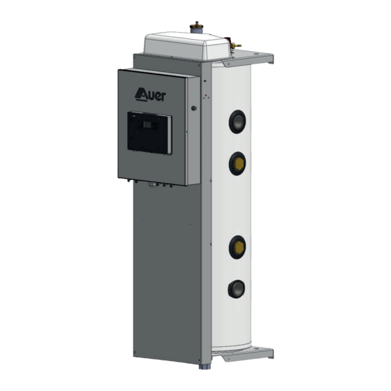
- Page 1 6P10 PILOT Hydraulic pilot for heat pumps 6P10 Installation manual 78 liters - 10 hydraulic outlets 6kW electrical back-up Ref. 753040 Made in France Manual réf. : 1898468 N° édition : 22.29...
-
Page 2: Table Of Contents
SOMMAIRE 1-SAFETY ............. 4 4.2.2.3 - UPMXL 25-125 circulator for heat pump circuits and distribution (DHW/heating) ............13 2 -PLEASE READ IMMEDIATELY ......6 4.2.2.3.1 - Manometric height/Flow rate ........13 2.1 - Conservation of documents ............6 4.2.2.3.2 - Setting of the circulator pump 2.2 - Symbols used ..................6 on the CP3 constant pressure mode......13 2.3 - Abbreviations and acronyms ............6... - Page 3 6.5.3 - Ambient temperature and heating circulation control functions ..26 A2.5 - CASE n°5 - 1 HRC70 heat pumps + 2 DHW tanks + 1 heating circuit ..39 6.5.3.1 - Ambient temperature sensor hysteresis........26 A2.6 - CASE n°6 - 1 HRC70 heat pumps + 1 DHW tank..........40 6.5.3.2 - Circulator pump speed ................26 A2.7 - CASE n°7 - 1 HRC70 heat pumps + 2 DHW tanks ........41 6.5.3.3 - Heating circulator control ..............26...
-
Page 4: 1-Safety
Danger of death if the pressure relief valves 1-SAFETY are missing or defective A defective pressure relief valve may prove Danger resulting from improper qualifi cations dangerous and could lead to burns or other injuries by, for example, the pipes bursting. •... - Page 5 Maintenance - Troubleshooting Maintenance and cleaning of the pilot must be carried out at least once a year by a qualifi ed professional. This appliance is in compliance with the international standards concerning electrical safety CEI 60335-1, CEI 60335-2-102. The CE branding on the appliance attests to its compliance with the following directives: - Low voltage (LV): 2014/35/UE...
-
Page 6: -Please Read Immediately
Admissible storage and transport temperatures are from -20°C to +60°C. The 6P10 Pilot must be stored on its original pallet. It must be This technical installation manual forms part of the appliance which transported on its pallet, empty of water, horizontally. It must remain it refers to. -
Page 7: Introduction
Ensure to keep the original delivered USB fl ash drive. 6P10 pilot is equipped with : It will facilitate your exchanges with your technical contacts. - One 78 liters wall tank with air bleed, pressure sensor, pilot sensor, 6kW electrical back-up, 6bars pressure relief valve and settling valve. -
Page 8: Operating Principles
4 - INSTALLATION 3.5 - Operating principles 4.1 - Placement choice 4.1.1 - Appropriate placement choice The Pilot must be placed in an area which is free from frost and adverse weather conditions. It must be placed as close as possible to the heat pump without exceeding the maximum distance. -
Page 9: Dimensions
4.1.3 - Dimensions 4.2 - Hydraulic installation The pilot must be placed at least 200mm above the fl oor or any Consult the hydraulic schematic diagrams in the appendix. obstacle the enable it to be drained. It must be placed at least 400mm under the ceiling to facilitate 4.2.1 - Recommendations the access to the air bleed and to the electrical back-up. -
Page 10: Frost Protection
4.2.1.7 - Frost protection Central heating installations must be cleaned Frost protection is necessary if the pilot is switched off during the in order to eliminate debris (copper, fi lings, winter months (ex: secondary residence, etc...). soldering waste) related to the set-up of the installation or from chemical reactions between the If the appliance is connected to an metals. -
Page 11: Installation Of The Dhw Circuit
4.2.1.10 - Installation of the DHW circuit mandatory It is to refer to the technical manual provided with each water tank. mandatory It is to install a safety group on the cold water inlet of each water tank. Do not place a stop valve between the safety group and the water tank. •... -
Page 12: Filter On The Water Inlet Of Each Heat Pump (Supplied)
As a reminder, depending on your installation, it is possible to rotate 4.2.1.13 - Filter on the water inlet of each the pilot’s buff er tank to place 1 to 6 plumbing fi ttings on the right heat pump (supplied) and 7 to 10 ones on the left : mandatory It is... -
Page 13: Distribution Circuits Connection (Dhw/Heating)
Perte Ballon Surface Puissance* Pertes Conso ation Réf. Qpri aire de charge sanitaire échangeur à Qpri aire à l'arrêt UA d'entretien à Qpri aire AUER litre ² kWh/24h 353000 3,15 0,23 1,77 2,52 4,10 0,30 2,78 3,00 342104 342150 3,76... -
Page 14: Electrical Connections
4.3.3 - Power electrical connection of the pilot 4.3 - Electrical connections Electrical supply must be protected by an omni-polar power cut- off device having a 3mm minimum spacing (EN 60335.1) : fuses or 4.3.1 - Power electrical connections circuit breakers must be calibrated according to the power of the pilot. -
Page 15: Power Connection Of The Hrc Heat Pump
Terminal block Three phase power supply : The terminals connection are «Cage Clamp» terminals spring. For Handling, use the following : - for 2.5mm² or 4mm² control terminals, use a 3.5 x 0.5mm fl at-head screwdriver. - for 6mm² power terminal, use a 5.5 x 0.8mm fl at-head screwdriver. -
Page 16: Cascade Of Heat Pumps
Plan for the appropriate length of cable between the pilot - Connect the two wires of the connecting cable on terminals and the heat pump. Do not hesitate to cut the cable to of the «Modbus» terminal while taking care to respect of the Pilot to be connected to the appropriate length to AVOID LOOPS. -
Page 17: Connection Of Circuits And Accessories
4.4 - Connection of circuits and accessories Sensors and accessories details : = Zone 1 control (ambience thermostat or water tank sensor ) = Zone 2 control (ambience thermostat or water tank aquastat) = Zone 3 control (water tank sensor) = Peak hours contact 9-10 = Outdoor sensor... -
Page 18: Set-Up
5 - SET-UP 5.3 - Starting set-up The pilot is factory confi gured to work with : - Heat pump without back-up boiler - 1 heating circuit Set-up must be done by a qualifi ed professional. This confi guration can be modifi ed, if necessary, in the Installer menu. -
Page 19: Step 3 : Filling
5.3.3 - Step 3 : Filling 5.4 - First use Activate the backfl ow prevention device of the installation to fi ll the To turn on the Pilot, press heating circuit to just over 1.5 bars of pressure. puts the Pilot in standby mode. Long pressing During the filling stage, the Pilot FILLING... -
Page 20: Settings And Functions
6 - SETTINGS AND FUNCTIONS 6.1 - Control panel 6.1.1 - Keypad Primary function Secondary function (short press) (long press) - menu access locking / unlocking of the - return / cancel keypad - switch on standby mode - setting the program scheduled temperatures comfort modes... -
Page 21: Menus
6.3 - Actions to be activated using a 6.2 - Menus combination of buttons access Menus (and sub-menus) combination of buttons Action buttons User menu Reset counters to zero in the «counters» menu INSTALLer menu Certain counters cannot be reset to zero. Only (Display here under will be shown or hidden according to the counters which can be reset are aff ected by press for 5s... -
Page 22: List Of Parameters Which Can Be Set
6.4 - List of parameters which can be set Factory Parameter N° Description Unit Range of setting setting P202 11 to 25 Maximum exterior temperature (warmest day for heat curve) °C P203 -30 to 10 Minimum exterior temperature ( (coldest day for heat curve)) °C auto: changeover is done automatically based on the P204... - Page 23 Factory Parameter N° Description Unit Range of setting setting 0: no pressure sensor 1: IMIT/HUBA sensor (4 bar) P226 Choice for pressure sensor 2: ELTEK sensor (4 bar) 3: 6 bar sensor P227 10 to 100 Speed of heat pump circulator pump P228 Post-circulation of the heat pump circulator pump Do not change the setting...
- Page 24 Factory Parameter N° Description Unit Range of setting setting Circuit 2 - Lowering in ECO: temperature lowering applied to P256 0 to P257 °K the heating setpoint during ECO mode. Circuit 2 - Lowering in Frost protection : temperature P257 P256 to 40 lowering applied to the heating setpoint during Frost °K protection mode...
-
Page 25: Description Of Functionalities
6.5.1.2 - Lowering of the temperature 6.5 - Description of functionalities The set temperature of heating can be lowered at the same time as 6.5.1 - Functions related to heating the ambient temperature when in Eco or Frost protection modes to improve the heat pump’s performance. -
Page 26: Automatic Summer/Winter Changeover
6.5.2.2 - Automatic summer/winter changeover 6.5.4 - Functions related to the production of domestic hot water With the automatic summer/winter changeover function activated, the pilot decides when to enact the changeover from one season 6.5.4.1 - Domestic priority sharing to another, independently from the choice made by the user via Allows the operation of the heating circuit at the end of the domestic the on/off button. -
Page 27: Maintenance And Troubleshooting
T_RETURn Temperature at heat pump inlet 1) Get the USB stick that comes with T_air Temperature of heat pump air the 6P10 pilot. t_evapor Temperature of evaporator 2) Insert the key into t_comp 1 Temperature of compressor the USB port (on (compressor n°1 if using heat pumps with 2... -
Page 28: Water Sensors
Counter n° Description Unit 7.1.3 - Water sensors C-23 Operating time of compressor n°1 Ohmic values for T_pilote (pilot outlet) and T_water (domestic C-24 Operating time of compressor n°2 water sensor placed in the tank) sensors C-25 Defrosting cycles quantity 10 K à... -
Page 29: Errors Indicated By The Pilot
7.1.7 - Errors indicated by the pilot Press to stop the sound signal (the error persists) Whatever the number of connected heat pumps, errors denomination is the same. If several heat pumps are connected, error alternately appears with the heat pump which is concerned. Display Error Possible causes... - Page 30 Press for 2 seconds to remove the errors manually (indicated by «press »). Display Error Possible causes Consequences Reset - The hydraulic connection between the heat pump rev. flow Flow rate is reversed and the pilot is reversed heat pump stopped* manual - The heat pump’s inlet and outlet sensors are reversed - The heat pump’s evaporator or the grills of the...
- Page 31 Display Error Possible causes Consequences Reset evap. senso. Defrosting sensor error Error when measuring the evaporation temperature heat pump stopped* manual - The exterior sensor is badly positioned and is being ext. senso. Exterior sensor placement error infl uenced by heat or cold sources informative message manual diag...
-
Page 32: Spare Parts
8 - SPARE PARTS Rep. Réf. Désignation B1239277 1’’1/2 valve 2 pces 1’’1/2 --> 1’’1/2 plumbing B1593083 fi tting UPMXL 25-125 PWM circulator B1244897 pump B1239236 1’’1/2 check valve B1134481 1’’1/2 plumbing fi tting PWM hydraulic set (for HRC 25kW B4994834 and 32kW) B1239216... -
Page 33: Warranty
Cases (not limited) for exclusion from warranty: The warranty only applies to parts which we (AUER) identify as having • Faulty electrical connection which does not conform to the national been defective at manufacture. If necessary, the part or product should standards in eff ect. -
Page 34: Appendix
APPENDIX A1 - Technical specifi cations A1.1 - General characteristics 6P10 Electrical supply 230V mono 400V tri Power supply cable cross- 3 G 6 mm² up to 5 G 2.5 mm² up section 3 G 10 mm² to 5 G 4 mm² Circuit braker Buff er tank Dimensions (W x H x D) -
Page 35: A2 - Schémas De Principe Hydraulique
A2 - Schémas de principe hydraulique How to fi nd the schematic corresponding to your installation... Access by list : heat pumps heating circuits Domestic hot water total number of CASE n° page number number circuits number circuits Access by table : 1 circuit 2 circuits 3 circuits... -
Page 36: A2.1 - Case N°1 - 1 Hrc
A2.1 - CASE n°1 - 1 HRC heat pump + 1 heating circuit CONFIGURATION: C-1 Radiator A-1 thermostat C-2 INACTIV C-3 INACTIV Heating circuit circulating pump Radiators heating circuit Spil Back-up boiler (optional) Pilot pressure relief valve *Cpac : Heat pump 2 circulating pump Room thermostat Tpil External sensor... -
Page 37: A2.2 - Case N°2 - 1 Hrc
A2.2 - CASE n°2 - 1 HRC heat pumps + 2 heating circuits CONFIGURATION: C-1 Radiator A-1 thermostat C-2 Radiator A-2 thermostat C-3 INACTIV Heating circuit circulating pump n°1 Heating circuit n°1 (radiators) Heating circuit circulating pump n°2 Heating circuit n°2 (radiators) Spil Back-up boiler (optional) Pilot pressure relief valve... -
Page 38: A2.3 - Case N°3 - 1 Hrc70 Heat Pump + 1 Dhw Tank + 1 Heating Circuit
A2.3 - CASE n°3 - 1 HRC70 heat pump + 1 DHW tank + 1 heating circuit CONFIGURATION: C-1 TANK A-1 aquastat C-2 Radiator A-2 thermostat C-3 INACTIV Aqs1 : Aquastat DHW tank (Ctrl 1) (or Tbal = sanitary sensor) Heating circuit (radiators) DHW tank circulating pump (ou C3) Boiler pressure relief valve... - Page 39 A2.5 - CASE n°5 - 1 HRC70 heat pumps + 2 DHW tanks + 1 heating circuit CONFIGURATION: C-1 TANK A-1 aquastat C-2 Radiator A-2 thermostat C-3 TANK A-3 sonde Aqs1 : Circuit 1 - DHW tank controlled by aquastat Air bleed DHW recirculating loop Circuit 2 - chauff age (radiators)
-
Page 40: A2.6 - Case N°6 - 1 Hrc70 Heat Pumps + 1 Dhw Tank
A2.6 - CASE n°6 - 1 HRC70 heat pumps + 1 DHW tank CONFIGURATION: C-1 TANK A-1 aquastat C-2 INACTIV C-3 INACTIV Aqs1 : Aquastat du DHW tank Boiler pressure relief valve Secs : Circulateur primaire du DHW tank Domestic water pressure relief valve CAR : Spil Check valve... -
Page 41: A2.7 - Case N°7 - 1 Hrc70 Heat Pumps + 2 Dhw Tanks
A2.7 - CASE n°7 - 1 HRC70 heat pumps + 2 DHW tanks CONFIGURATION: C-1 TANK A-1 aquastat C-2 TANK A-2 aquastat C-3 INACTIV Aqs1 : Circuit 1 - DHW tank controlled by aquastat Filter Aqs2 : Contrôle circuit 2 - Aquastat DHW tank 2 Air bleed DHW recirculating loop Boiler pressure relief valve... -
Page 42: A2.8 - Case N°8 - 1 Hrc70 Heat Pumps + 3 Dhw Tanks
A2.8 - CASE n°8 - 1 HRC70 heat pumps + 3 DHW tanks CONFIGURATION: C-1 TANK A-1 aquastat C-2 TANK A-2 aquastat C-3 TANK A-3 sonde Aqs1 : Circuit 1 - DHW tank controlled by aquastat Air bleed Aqs2 : Circuit 2 - DHW tank controlled by aquastat Boiler pressure relief valve DHW recirculating loop... -
Page 43: A2.9 - Case N°9 - 2 Hrc70 Heat Pumps + 1 Heating Circuit
A2.9 -CASE n°9 - 2 HRC70 heat pumps + 1 heating circuit CONFIGURATION: C-1 radiator A-1 thermostat C-2 INACTIV C-3 INACTIV Heating circuit circulating pump Air bleed Back-up boiler (optional) Radiators heating circuit *Cpac : Spil Heat pump 1 circulating pump (PWM signal) Pilot pressure relief valve *Cpac2 Heat pump 2 circulating pump... -
Page 44: A2.10 - Case N°10 - 2 Hrc70 Heat Pumps + 2 Heating Circuits
A2.10 -CASE n°10 - 2 HRC70 heat pumps + 2 heating circuits CONFIGURATION: C-1 radiator A-1 thermostat C-2 Radiator A-2 thermostat C-3 INACTIV Circuit 1 - heating circuit circulating pump Circuit 1 - radiators heating circuit Circuit 2 - heating circuit circulating pump Circuit 2 - radiators heating circuit Spil Back-up boiler (optional) -
Page 45: A2.11 - Case N°11 - 2 Hrc70 Heat Pumps + 3 Heating Circuits
A2.11 -CASE n°11 - 2 HRC70 heat pumps + 3 heating circuits CONFIGURATION: C-1 radiator A-1 thermostat C-2 INACTIV C-3 INACTIV Circuit 4 - heating circuit circulating pump 2ème heating circuit (radiators) Circuit 5 - heating circuit circulating pump 3ème heating circuit (radiators) Spil Circuit 6 - heating circuit circulating pump Pilot pressure relief valve... -
Page 46: Heating Circuit
A2.13 -CASE n°13 - 2 HRC70 heat pumps + 1 DHW tank + 1 heating circuit CONFIGURATION: C-1 TANK A-1 aquastat C-2 Radiator A-2 thermostat C-3 INACTIV Aqs1 : Circuit 1 - DHW tank controlled by aquastat Air bleed Circuit 1 - DHW primary circulating pump Heating circuit (radiators) Secs : Circuit 2 - heating circuit circulating pump... -
Page 47: Heating Circuit
A2.16 -CASE n°16 - 2 HRC70 heat pumps + 2 DHW tanks + 1 heating circuit CONFIGURATION: C-1 TANK A-1 aquastat C-2 Radiator A-2 thermostat C-3 INACTIV Aqs4 : Circuit 4 - DHW tank controlled by aquastat Filter Aqs5 : Circuit 5 - DHW tank controlled by aquastat Air bleed Secs :... -
Page 48: A2.18 - Case N°18 - 2 Hrc70 Heat Pumps + 1 Dhw Tank
A2.18 -CASE n°18 - 2 HRC70 heat pumps + 1 DHW tank CONFIGURATION: C-1 TANK A-1 aquastat C-2 INACTIV C-3 INACTIV Aquastat DHW tank Air bleed Circuit 1 - DHW primary circulating pump Boiler pressure relief valve CAR : Spil Check valve Pilot pressure relief valve Back-up boiler (optional) -
Page 49: A2.19 - Case N°19 - 2 Hrc70 Heat Pumps + 2 Dhw Tanks
A2.19 -CASE n°19 - 2 HRC70 heat pumps + 2 DHW tanks CONFIGURATION: C-1 TANK A-1 aquastat C-2 TANK A-2 aquastat C-3 INACTIV Aqs1 : Circuit 1 - DHW tank controlled by aquastat Filter Aqs2 : Contrôle circuit 2 - aquastat DHW tank 2 Air bleed Circuit 1 - DHW primary circulating pump Boiler pressure relief valve... -
Page 50: A2.20 - Case N°20 - 2 Hrc70 Heat Pumps + 3 Dhw Tanks
A2.20 -CASE n°20 - 2 HRC70 heat pumps + 3 DHW tanks CONFIGURATION: C-1 TANK A-1 aquastat C-2 INACTIV C-3 INACTIV Aqs4 : *Cpac2 Circuit 4 - DHW tank controlled by aquastat Heat pump 2 circulating pump Aqs5 : Circuit 5 - DHW tank controlled by aquastat Filter Aqs6 : Circuit 6 - DHW tank controlled by aquastat... -
Page 51: A2.22 - Case N°22 - 3 Hrc70 Heat Pumps + 1 Heating Circuit
A2.22 -CASE n°22 - 3 HRC70 heat pumps + 1 heating circuit CONFIGURATION: C-1 radiator A-1 thermostat C-2 INACTIV C-3 INACTIV Heating circuit circulating pump (radiators) Air bleed CAR : Check valve Heating circuit (radiators) Back-up boiler (optional) Spil Pilot pressure relief valve Cpac1 : Heat pump 1 circulating pump (PWM signal) Room thermostat... -
Page 52: A2.23 - Case N°23 - 3 Hrc70 Heat Pumps + 2 Heating Circuits
A2.23 -CASE n°23 - 3 HRC70 heat pumps + 2 heating circuits CONFIGURATION: C-1 radiator A-1 thermostat C-2 INACTIV C-3 INACTIV Circuit 4 - heating circuit circulating pump Circuit 4 - heating circuit (radiators) Circuit 5 - heating circuit circulating pump Circuit 5 - heating circuit (radiators) CAR : Check valve... -
Page 53: A2.24 - Case N°24 - 3 Hrc70 Heat Pumps + 3 Heating Circuits
A2.24 -CASE n°24 - 3 HRC70 heat pumps + 3 heating circuits CONFIGURATION: C-1 radiator A-1 thermostat C-2 INACTIV C-3 INACTIV Circuit 4 - heating circuit circulating pump Circuit 4 - heating circuit (radiators) Circuit 5 - heating circuit circulating pump Circuit 5 - heating circuit (radiators) Circuit 6 - heating circuit circulating pump Circuit 6 - heating circuit (radiators) -
Page 54: A2.25 - Case N°25 - 3 Hrc70 Heat Pumps + 1 Dhw Tank
A2.25 -CASE n°25 - 3 HRC70 heat pumps + 1 DHW tank CONFIGURATION: C-1 TANK A-1 aquastat C-2 INACTIV C-3 INACTIV Aquastat DHW tank Filter Circuit 1 - DHW primary circulating pump Air bleed CAR : Check valve Spil Pilot pressure relief valve Back-up boiler (optional) Tpil Pilot temperature sensor... -
Page 55: A2.26 - Case N°26 - 3 Hrc70 Heat Pumps + 2 Dhw Tanks
A2.26 -CASE n°26 - 3 HRC70 heat pumps + 2 DHW tanks CONFIGURATION: C-1 TANK A-1 aquastat C-2 INACTIV C-3 INACTIV Aqs4 : Circuit 4 - DHW tank controlled by aquastat Domestic Cold Water Aqs5 : Circuit 5 - DHW tank controlled by aquastat Filter Circuit 4 - DHW primary circulating pump Air bleed... -
Page 56: A2.27 - Case N°27 - 3 Hrc70 Heat Pumps + 3 Dhw Tanks
A2.27 -CASE n°27 - 3 HRC70 heat pumps + 3 DHW tanks CONFIGURATION: C-1 TANK A-1 aquastat C-2 INACTIV C-3 INACTIV Aqs4 : Circuit 4 - DHW tank controlled by aquastat Domestic Cold Water Aqs5 : Circuit 5 - DHW tank controlled by aquastat Filter Aqs6 : Circuit 6 - DHW tank controlled by aquastat... -
Page 57: A3 - Wiring Diagram
A3 - Wiring diagram *Cpac must not be connected in the case of the HRC 40kW heat pump (circulator integrated into the heat pump) 6P10 PILOT MANUAL... -
Page 58: A4 - Recap Of Functions
A4 - Recap of functions A4.1 - Control panel A4.1.1 - Keypad Primary function Secondary function (short press) (long press) - menu access locking / unlocking of the - return / cancel keypad - switch on standby mode - setting the program scheduled temperatures comfort modes... -
Page 59: Menus
A.4.2 - Menus A.4.3 - Actions through key combinations access combination of Menus (and sub-menus) Action buttons buttons User menu Reset counters to zero in the «counters» menu Certain counters cannot be reset to zero. Only INSTALLer menu the counters which can be reset are aff ected by press for 5s (Display here under will be shown or hidden according to this action. - Page 60 Industrial and development site Rue de la République CS 40029 80210 Feuquières-en-Vimeu Technical assistance department* E-mail : enr@auer.fr *Technical assistance is reserved for professionals...
Need help?
Do you have a question about the 6P10 PILOT and is the answer not in the manual?
Questions and answers