
Summary of Contents for MESA LABORATORIES PQ 200
- Page 1 PQ 200 Air Sampler User Manual U.S. EPA FRM Designated Sampler RFPS-0498-116 RFPS-1298-125 Mesa Laboratories, Inc. 12100 West 6th Ave. Lakewood, CO 80228 www.MesaLabs.com MK101-05 Rev B...
- Page 2 NOTICE This manual pertains to the Revision U(C8445) version of the PQ200. Refer to the table of contents for information on previous versions of the sampler. Customer Support and Technical Assistance For technical assistance or to request repairs or replacement parts, contact Mesa Labs at (973) 492-8400, or by e-mail at csbutler@mesalabs.com.
-
Page 3: Table Of Contents
Table of Contents Section Page Introduction………………………………………………………………………………………………………………………...5 Instrument Description………………………………………………………………………………………………………… 6 Specifications……………………………………………………………………………………………………………………..10 Safety……………………………………………………………………………………………………………………………….10 Setup 5.1. Initial Setup Instructions……………………………………………………………………………………………………………...10 5.2 Initially Powering the PQ200……………………………………………………………………………….………………………..15 5.3 Setting the Date and Time…………………………………………………………………………………………………………...15 5.4 Entering Site and Filter Information……………………………………………………………………………………………….15 5.5 Initial Performance Checks……………………………………………………………………………………………………………15 Operation 6.1 Run the Sampler from Midnight to Midnight……………………………………………………………………….…………...17 6.2 Run the Sampler with User-Defined Start/Stop Times……………………………………….………………………………18 6.3 While the PQ200 is Running…………………………………………………………………………………………………………..18 6.4 Temporary Halt Then Continue Sampling………………………………………………………………………………………..19... - Page 4 Appendix K Updating Main Controller Board to “Rev U”………………………………………………………………71 Appendix L Instructions for PM Sampling…………………………………………………………………………..77 coarse Appendix M Leak Test Procedure for S’Ns 906 through 1016……………………………………………………….79 Appendix N Rev “D” PCBs Calibration and Parts…………………………………………………………………………81 Appendix O WINS Installation………………………………………………………………………………………………….85 Appendix P Pump Rebuild Instructions……………………………………………………………………………………..87 Appendix Q Revision T Manual…………………………………………………………………………………………………97...
-
Page 5: Introduction
1.0 Introduction The purpose of this manual is to provide complete operation, calibration, and maintenance details for the BGI PQ200 air sampler. This instrument has been specifically designed to meet or exceed the operational requirements of a Reference Method sampling device under 40 CFR Part 50, Appendices J and L. For additional guidance on sampler operation, recommended maintenance, and procedures for filter handling and weighing, refer to the EPA Quality Assurance Handbook Volume II The PQ200 is a microprocessor-controlled air sampling instrument capable of sampling TSP, PM... -
Page 6: Instrument Description
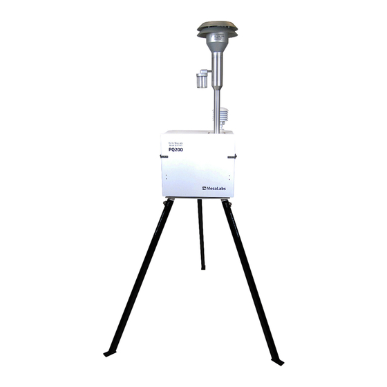
2.0 Instrument Description Your PQ200 comes with the following: PQ200 sampler Downtube inlet with water jar VSCC or PM adapter installed in filter assembly (model dependent) 12V battery Filter cassette AC power adapter Legs (3) Ambient temperature sensor with radiation shield Leak test kit (flow audit adapter and filter cassette plus rubber discs) Download cable The components and basic instrument operation are as follows:... - Page 7 lower housings ensure a tight seal around the filter cassette. The filter cassette ® itself is made of Delrin and has upper and lower sections which snap together. These two halves sandwich a single 47 mm filter and a stainless-steel screen which serves as a backing/support plate for the filter.
- Page 8 temperature decreases. When used as a voltage divider, this circuit will produce a linear output voltage proportional to temperature. Resistor R2 and thermistor TH2 provide compensation for the typically narrow range of this simple approach providing a total accurate range of -30° to +50° C with a linearity deviation of +/- 0.16°...
- Page 9 Charger/External power supply is plugged in, the screen will display [DC In] or toggle between [DC In] and [Charged] depending on the internal battery status. While running from external batteries, the display will show EXT xx% indicating the approximate capacity of the external battery. A switching circuit within the PQ200 will automatically detect how the unit is powered and will display appropriately.
-
Page 10: Specifications
3.0 SPECIFICATIONS PQ200 sampler weight: 48 lbs (21.8 kg) Inlet and downtube weight: 5.5 lbs (3.4 kg) Legs weight: 8 lbs (3.6 kg) Complete system weight: 61.5 lbs (27.9 kg) Enclosure Dimensions: 16 x 19 x 18 inches (41.1 x 48 x 47 cm) Height of inlet above ground: 6.56 ft (2 m) Display:... - Page 11 Step 1. Attach the legs to the unit at the three hard points on the underside of the sampler. The legs are identical and interchangeable. Make sure the connectors are seated properly and that the legs are securely attached. Step 2. Attach the AC power supply to the rear of the unit underneath the fan cowling.
- Page 12 Step 3. Attach the external temperature gauge to the rear of the unit. The attachment points are on the fan cowling itself. Position the temperature gauge assembly so that it sits above the top of the sampler case. Screw the connectors firmly into the attachment points.
- Page 13 Step 6. The VSCC assembly is installed prior to shipment with model PQVSCC. Open the VSCC and filter assembly inside the PQ200 sampler case by carefully rotating the handle counterclockwise using both hands. Inspect the VSCC for obvious missing pieces or damage. Ensure the interior of the VSCC is clean and clear of any debris.
- Page 14 Figure 2. Exploded View of Components Installed in the Back of the Instrument...
-
Page 15: Initially Powering The Pq200
5.2 Initially Powering the PQ200 Press the ON/OFF button on the PQ200. The screen should light with the message: PQ200 Air Sampling System (c)Copyright 1998 BGI Incorporated All Rights Reserved Serial Number: XXXX Version: X.XX After a few seconds, the main screen will appear. The main screen always displays the ambient barometric pressure, ambient and filter temperatures, date, time, power source, and any flags that may have occurred. -
Page 16: Initial Performance Checks
5. Press the EXIT button again to return to the home screen. NOTE: The site and filter information may also be entered using the PQ200 Job Controller software (Appendix H), through OTG Flash Drive (section 6.2), or through the computer using a terminal program (Appendix I). -
Page 17: Operation
6.0 Operation Run the Sampler from Midnight to Midnight For most applications, this is the appropriate method of operation. It complies with the EPA’s requirement for 24-hour sampling. The run will commence at the next occurrence of midnight (00:00) and will stop sampling at midnight of the following day. -
Page 18: Run The Sampler With User-Defined Start/Stop Times
procedure will not work if another type of USB is utilized. To adjust PQ200 settings, follow the steps below: 1. Open Notepad on your computer. 2. The document MUST start with <begin> and end with <end>. 3. Write values that you would like to customize. The options are listed below: a. -
Page 19: Temporary Halt Then Continue Sampling
Pressing the select button will display a second screen: Tmax:28.5 Tmin:28.2 Tavg:28.4 BPmax:750 BPmin:749 BPavg:749 2017 Q(Vlpm):16.70 AVG:16.71 CV 0.16 04jul 749mmHg A28.6°C F27.8°C SP025cm 15:05 Where: elapsed time since the current run started total volume sampled during the current run [DC In]: current power source from which the sampler is operating Start:... -
Page 20: Ending A Run
From the home screen, press SELECT to access the main menu. • From the main menu, scroll down by pressing the down arrow button and select * Continue • Current Run The sampler will then resume the run. However, observe that the elapsed time did not change while the unit was halted. -
Page 21: Data Download Using The Pq200 Menu
Using a serial (9-pin) cable (female-female DL02), or a USB cable(accessory P/N: USB A/B), • connect the PQ200 sampler to a computer with the PQ200 Job Controller Program. The USB port is located on the edge of the circuit board. To access it, unscrew the two thumb screws at the top of the front panel and gently pull the panel forward to expose the circuit board, taking care not to pull on any of the wire connections. -
Page 22: Calibration
6.6.4 Data Download Using Serial Communication Commands After the sampler has completed its run, the data is available for download. To download the data using serial communication commands, follow the steps below: 1. Connect an RS-232 or USB type B cable between the PC and PQ200 2. -
Page 23: Flow Rate Calibration
Flow Rate 7.1.1 Manual Flow Rate Calibration To calibrate the flow rate of your PQ200, follow the steps outlined below: 1. Remove the size selective inlet from the top of the downtube, leaving the downtube in place. 2. Turn on your calibration device and install on downtube. A BGI deltaCal is preferable for PQ200 calibration. -
Page 24: Verifying Flow Rate
LPM. The calibration for 16.7 LPM should be performed last. 7.1.2 Automatic Flow Rate Calibration To use the automatic calibration feature on your PQ200, you must use a deltaCal and accessory cable (70066). To calibrate, follow the steps outlined below: 1. -
Page 25: Temperature Probe
Temperature Probe Note: See Appendix Q for earlier rev “T” PCBs See Appendix N for earlier rev “D” PCBs 7.2.1 Verifying Temperature You will need a NIST-traceable thermometer, such as that included with the BGI deltaCal calibrator, for both the verification and calibration of the PQ200 temperature probes. To verify the ambient temperature sensor, allow the temperature probe to reach equilibrium with the ambient air. -
Page 26: Barometric Pressure
Barometric Pressure Note: See Appendix Q for earlier rev “T” PCBs See Appendix N for earlier rev “D” PCBs 7.3.1 Pressure Calibration and Verification You will need a NIST-traceable barometer, like that included with the BGI deltaCal calibrator. Compare the ambient pressure reading on the PQ200 main screen with the pressure reading on the traceable barometer. -
Page 27: Internal Leak Test
4. The PQ200 LEAK TEST: In Progress! Plug the Inlet Now! Press <Select> Key to Continue! screen will be displayed. Ensure that the valve is closed on the flow audit adapter and press SELECT to begin evacuating the system. 5. After pressing SELECT, the PQ200 LEAK TEST: In Progress! Creating the Initial Vacuum…. -
Page 28: Updating Firmware
download from the PQ200 sampler. Pump cumulative time is shown when either printing or screen viewing a download. When this time exceeds 8,000 hours the pump should be rebuilt. The rebuild is a relatively easy task and requires the replacement of diaphragms, valves, and bearings. Depending on which components need replacing, we offer three rebuild kit levels. -
Page 29: Troubleshooting
memory address has been written. Once complete, the terminal program will display Completed. Resetting. Disconnect serial cable and press the ON/OFF button on the PQ200 to restart. 9.0. TROUBLESHOOTING Problem: Selecting Run the Sampler from Midnight to Midnight or Run Sampler w/ User Defined Start/Stop causes the unit to shut down. - Page 30 the oil as possible. Under no circumstances should any spray lubricants be utilized. Problem: The pump is running rough or will not maintain a stable flow rate. Solution: Disassemble the pump and clean out any debris. Inspect the motor and replace components that show signs of wear.
-
Page 31: Warranty
10.0. Warranty Mesa Labs warrants equipment of its manufacture and bearing its nameplate to be free from defects in workmanship and material. We make no warranty, express or implied, except as set forth herein. Mesa's liability under this warranty extends for a period of one (1) year from the date of product’s shipment. Mesa Labs warrants service performed on equipment at our factory for a period of ninety (90) days and spare parts for a period of sixty (60) days. -
Page 32: Appendix A Parts List And Blow-Out Figures
Appendix A Parts List and Exploded Drawing Figures... - Page 33 Figure A1. Filter Holder with PM Adapter Installed...
- Page 34 Figure A2. PQ200 Pump Exploded Drawing...
- Page 35 Figure A3. Instrument Panel Exploded Drawing...
- Page 37 Figure A5. PM Size Selective Inlet...
- Page 38 Figure A6. Current Model Cables...
- Page 39 Figure A7. Current Model Cables...
- Page 40 Figure A8. Current Model Cables...
- Page 41 AMBIENT FILTER FLOW RS232 DISPLAY TEMP TEMP SENSOR PROBE PROBE BUTTONS BACKLIGHT SOLENIOD VALVE TYPE B FILTER PUMP CHARGER TYPE A BATTERY Figure A9. Location of cable connections on PCB...
- Page 42 Figure A10. Location of cable connections on Rev T PCB (Obsolete)
- Page 43 DET. # FIG. PART # DESCRIPTION SC1001 #10-32 X 1/2" Allen Cap Screws A1590 Filter Holder Top Plate A1754 PM10 Upper Impactor Housing B1755 PM10 Lower Impactor Housing A1609 Bushing (upper) SP1002 Spring A1625 Assembly Rod A1591 Filter Holder Upper Sliding Plate A1606 Lower Filter Holder SC1003...
- Page 44 DET. # FIG. PART # DESCRIPTION VITON036 O-RING BUNA135 O-RING SC1015 #8-32 X 1 1/4 Studs for Pump VITON030 O-RING A1644 Inside Panel C8445 Main Controller Board SC2001 #4-40 X 3/8 Phillips Pan Head Screw A1672 RS 232 Adapter Cable A2339 Display Screen (rev “T”...
- Page 45 DET. # FIG. PART # DESCRIPTION HO3020 9" Tygon Hose CT3021 External Pressure Connector NT3022 1/4-20 Wing Nut A1624 Clamp BT3023 Battery A1621 Battery Holder NT3024 5/16-18 Wing Nut SC3025 8-32 x 3/4 Long Nut PM3026 Pump Assembly 188229 Water Trap Drain NT3027 7/16-32 Hex Nut SC3028...
- Page 46 DET. # FIG. PART # DESCRIPTION PS15V6A 90W Power Supply 188055 Power Supply with Bracket Assembly RP4009 Rubber Protectors for Cable Wires A1647 Leg Sub Base W/ Short Legs & Ring SC4010 3/8-16 X 1 Hex Head Bolt GS4012 Stud Mount (1660) B1659 Gill Screen Bracket A1667...
-
Page 47: Pq200 Sampler Menu Tree
Appendix B PQ200 Sampler Menu Tree Status Screen Main Menu +-------Run Sampler From Midnight to Midnight +-------Run Sampler With Wiser Defined Start & Stop +-------Continue Current Run +-------Reset Run Data & Scheduled Run +-------Set Current Date & Time +-------Site & Filter Information +-------Set Logger Interval +-------Leak Test +-------Select Flow Rate... - Page 48 PQ200 Sampler Revision T Menu Tree (Obsolete) Status Screen Main Menu +-------Review Last Run Data and Conditions +-------Run Sampler from Midnight to Midnight +-------Test and Calibration Menu +---------Leak Test +---------Select and Calibrate a Flow Rate +---------Verify Flow Calibration +-------Set-Ups and Download +---------Run Sampler w/User Defined Start/Stop +---------Continue with Current Run +---------Download Now...
-
Page 49: Appendix C Filters And Weighing Procedure
Appendix C Filters and Weighing Procedure For exact compliance with EPA PM procedures, refer to 40 CFR Part 50, Appendix L, and Section 2.12 of EPA's Quality Assurance Handbook. Filters The filter should have the following characteristics: Size: Circular, 46.2 mm diameter ± 0.25 mm. Medium: Polytetrafluoroethylene (PTFE Teflon), with integral support ring. - Page 50 Filter Cassette Handling The filter cassettes provided for use with the PQ200 are as specified in 40 CFR 50 Appendix L, Figures L-27 through L-29. The upper and lower halves of the cassette have been designed with an interference fit to prevent the cassette from coming apart easily, therefore some care must be exercised when opening and closing the cassette, especially when a filter is inside.
-
Page 51: Appendix D Dip Switch Functions
Appendix D Rev T Dip Switch Functions (Obsolete) There is an 8-pole dip switch located on the left side of the main control board of the PQ200, in Figure 9 of this manual. When standing in front of the PQ200, with the front panel swung forward for inspection, the dip switch will be found to the lower left, on the board. - Page 52 Switch No. 2 Reset century. The PQ200 will automatically change to the year 2000. Switch No. 3 Half time running. Setting switch number 3 to "on" will cause the PQ200 to run for one minute and rest for one minute. The total elapsed hours will be correct and the accumulated volume will be one half of that expected over the elapsed time period.
- Page 53 Figure D2. PQ200 Dip Switch...
-
Page 54: Appendix E Use Of The Pq200 As A Pm
Appendix E Use of the PQ200 as a PM Designated Reference Sampler The PQ200 is an EPA designated reference sampler for PM and PM sampling. To perform PM sampling, the PM adaptor should be used instead of the VSCC. The PM adapter is merely a continuation of the 12-inch long straight tube connecting the inlet to the instrument. -
Page 55: Appendix F Solar Panel Power Supply
Appendix F Solar Panel Power Supply Introduction The 188095 solar panel kit is intended to permit the PQ200 to run for extended or indefinite periods of time depending on the available solar radiation at a given location. Because of the low current draw, The PQ200 is highly amenable to this technique. - Page 56 There are other factors which will reduce the energy replenishment of the system and make accurate performance predictions difficult. Amongst these are: 1. Dirt on the solar panel 2. Extreme cold weather affecting battery performance 3. Extremely high particulate loadings causing high filter resistance and consequent high current drain 4.
- Page 57 The other wire emanating from the box is equipped with a CPC connector. This wire is installed through the hole in the bottom of the PQ200 enclosure normally used for the power supply cable. This wire is installed in place of the power supply cable when running on solar power. Overall Operation and Troubleshooting Prior to deploying a PQ200 with solar panel, it is prudent to ensure that the internal battery is fully charged.
-
Page 62: Appendix G Accessories
Appendix G. Accessories Cassette Opener (CO1) In order to prevent filter damage due to dropping or touching the filter during the cassette disassembly procedure a cassette opener has been developed to provide a gentle opening action while keeping all components on the bench top. In use the opener is laid flat on the bench top such that the base pad elevates the "forks"... - Page 63 USB Download Cable (USB A/B) USB type A to USB type B cable to download data to a computer. The PQ200 uses and internal USB to RS232 converter. The first time a PQ200 is connected to a computer via the USB cable, it will need to install the drivers for the converter.
-
Page 64: Appendix Hpq200 Job Controller Software
Appendix H PQ200 Job Controller Software SUPPORTED HARDWARE The PQ200 Job Controller software program installs into any IBM PC or compatible computer running 32- bit Windows or 64-bit Windows in compatibility mode. The computer must have: COM1 or COM2, RS232 serial port for downloading •... - Page 65 User 1 and User 2 fields are designated by the EPA to be controlled by the person in the field operating the PQ 200 instrument and are to be held in the memory by the instrument. The software can be used to edit this field, but changes are not saved when job file is saved.
- Page 66 ambient temperature in degrees Celsius, and also the time at which this maximum differential occurred, even if it occurred after the completion of the sampling period. The "Flowrate Info in Lpm" box shows the target flow, the average flow achieved during the sample run, the coefficient of variation of the measured flow rates, and the total volume of air sampled in actual cubic meters.
-
Page 67: Appendix I Terminal Program Interface
Appendix I Terminal Program interface The PQ200 can be communicated with directly if the PQ200 Job Controller is not used. Run data is available for download, and new run settings can be entered. To configure the PC to communicate with the PQ200, follow the steps below: 1. -
Page 68: Very Sharp Cut Cyclone - Vscc Instructions For Use And Maintenance
Appendix J ® VERY SHARP CUT CYCLONE - VSCC Instructions for Use and Maintenance Introduction ® ® The BGI Very Sharp Cut Cyclone (VSCC ) is designed and manufactured only by Mesa Labs. The VSCC intended use is as an equivalent fine particulate matter separator in place of the US EPA WINS Impactor for PM sampling in any commercial model of the U.S. - Page 69 Operation ® After installation of the VSCC , the instrument may be run in the normal manner at a flow rate of 16.67 LPM as described in the manufacturers operation manual and 40CFR Part 53 specification. It ® actual is important to note the performance and operation of the VSCC is based on volumetric flow rate and not STP corrected flows.
- Page 70 Figure J2. Exploded Diagram of VSCC ® 1. Thorpe A. et al (2001) Effects of Dust Loading on the Performance of the VSCC Cyclone, Health & Safety Laboratory Report # IR/L/EXCON/O1/09...
- Page 71 Appendix K Updating Main Controller Board to Rev U(C8445) Upgrading from a pre Revision T Board PQ200 board Revision D and later can be updated to the current version. Boards prior to Revision T require the following hardware upgrade kit which includes the required main controller board: MESA P/N 188281 PARTS INCLUDED C8445...
- Page 72 board (79), display (64) and all cables from these boards. Discard boards and cables. Save screws. (See Figure K1) 5) Remove Ambient Sensor cable (A1680), External Power cable (A1679), Backlight Shunt cable with resistor (A1677), and Battery Cable (A1676). Discard all cables. Save the Resistor Clamp (143). Plug the two holes from the resistor clamp using existing screws and 2 nuts provided.
- Page 73 b) Calibrate temperatures, barometric pressure and flow. c) Program a run for 15 minutes. 12) You are now ready to start sampling. REPLACEMENT STEPS FOR REVISION T BOARDS 1) Remove all connectors and pressure sensor tubing from PC board. Be sure to identify each cable before removing it.
- Page 74 Figure K1. Exploded view of obsolete instrument panel configuration...
- Page 75 Figure K2. Exploded View of Instrument Panel...
- Page 76 Figure K3. Location of Low Voltage and Ambient Cables on Inside Panel Figure K4. Location of pressure hoses.
- Page 77 Appendix L Instructions for PM Sampling coarse is defined by the U.S. EPA as a regular PM concentration measurement with a concurrent PM coarse concentration measurement subtracted from it. Both concentration measurements are to be taken simultaneously and reported on a volumetric basis, i.e. under actual (ambient temperature & barometric pressure) rather than standardized conditions.
- Page 78 3. Data Reporting. Report concentrations to EPA as µg/m , at actual volume. Typically PM methods are reported in standard volume, however when sampling with two PQ200s for , both sample volumes are coarse reported in actual volumes. It is strongly recommended that you check to see the start and stop times of the PM and PM collocated PQ200s are within 15 minutes of each other.
- Page 79 Appendix M Leak Test Procedure for S/Ns 906 through 1016 On September 01, 2010 BGI changed the PQ200 External Leak Check procedure for Serial Numbers greater than S/N906. The electronic Solenoid Valve was removed and replaced with a manual valve to perform the external leak check procedure.
- Page 80 After 10 to 15 seconds the SP will rise to approximately 95 cm. When the SP reading displays 95 cm, “immediately” close the Leak Test valve near the filter holder by rotating the handle forward to the 9 o’clock position. After two seconds the screen will display LEAK TEST IN PROGRESS and the SP display should remain constant at a SP number of 95 to 100 cm.
- Page 81 Appendix N Rev “D” PCBs Calibration and Parts Temperature Probe Calibration Equipment for rev “D” PCBs The following apparatus is required to perform an accurate temperature calibration. • 4&1/2 digit, precision, calibrated, volt meter (recommend B&K Precision model #2945) • Total immersion, precision, NIST traceable thermometer •...
- Page 82 • A pair of hemostats Procedure for rev “D” PCBs • At the Main screen, compare the PQ200 barometric reading to that of the NIST traceable barometer (If the barometer reads in inches (typical US readings) multiply by 25.4 to obtain millimeters). Adjust the "OFFSET"...
- Page 83 Figure N1. Obsolete Cables from Rev D PCB...
- Page 84 Figure N2. Obsolete Cables from Rev D PCB...
- Page 85 Appendix O WINS Installation (Obsolete) • To open the WINS (Well Impactor Ninety-Six) and filter assembly inside the PQ200 sampler case, carefully rotate the handle counterclockwise using both hands. (CAUTION! Once the assembly has started to open, the weight of the two plates will tend to force the whole assembly open even further.) This will expose the WINS impactor and the filter cassette (see Figure 4).
- Page 86 impactor well is in good condition and maintains a tight fit. Replace if necessary. Wipe the exterior of the well with a clean Kimwipe. Transport the well to the sampler upright in a clean, protective container away from direct sunlight or extreme temperatures.
- Page 87 Appendix P Pump Rebuild Instructions 1. 1.0 Introduction The pump used in the BGI PQ100 and PQ200 air samplers is of Mesa design and manufacture. The only items not of Mesa manufacture are the motor and bearing for the eccentric. The basic design is a double diaphragm, steel reed valve, scotch yoke.
- Page 88 2. 3.0 Disassembly and Inspection All of the component parts of the pump are shown in Figure P1 and described in the parts list, Table 1. Four levels of repair/rebuild kit are made available. Other than the parts listed in the kits, it is not anticipated that any other components will be required except through physical damage or loss.
- Page 89 Step 1: To start rebuilding your pump, remove the two screws that secure the motor to the pump body. The motor assembly can now be pulled away from the pump body. Inspect the eccentric bearing for looseness on the shaft. Inspect the bearing for smooth rotation and absence of play.
- Page 90 lines on the face containing the motor or the mounting studs. If the motor also requires replacement after removing the eccentric bearing assembly, also remove the three motor plate screws which secure the motor plate to the motor. The new motor is attached to the plate utilizing the three screws just removed.
- Page 91 3.4 Diaphragm Removal Step 6: The diaphragms are removed by grasping the diaphragm retainer between the thumb and forefinger and rotating in a counter- clockwise direction when looking down at it. The other hand is used to grasp the same component on the opposite side.
- Page 92 the moment. Prepare the opposite diaphragm assembly and screw it into the yoke, holding each assembly between the thumb and forefinger of each hand. Each diaphragm may now be inserted into its respective recess. The edges of the disks are to be tucked into the recess in the pump body.
- Page 93 before the pump “turns over”. This is within normal limits but should only occur, if at all, during the first start up. If 30 seconds has been exceeded, shut down at once. The assembly procedures have not been correctly followed. If the pump runs but there is little or no air flow, check to ensure that one of the valve assemblies has not been reversed.
- Page 94 Table 1 List of PQ 100/200 Pump Parts DET.# QTY FIG. PART # DESCRIPTION B1292 Valve Upper Plate B1293 Valve Lower Plate A1288 Diaphragm Retainer A2187 Diaphragm A1289 Diaphragm Retainer Bushing B1283 Pump Housing A1287 Follower Yoke DDRI-6632 Bearing A1294 Eccentric SC0105 M4 X 4mm Set Screw...
- Page 95 Figure P1 – PQ200 Pump Exploded Drawing...
- Page 96 Figure P2 – Orientation of Valve Plates...
- Page 97 Appendix Q Revision T Manual (Obsolete) For sections not included in this appendix see manual main sections. 2.0 Instrument Description The PQ200 control panel and screen are menu driven for ease of operation. Complete control of the sampler is achieved through only six buttons: ON/OFF SELECT LIGHT...
- Page 98 From the Main menu, use the arrow keys until * Set-Ups and Download flashes. Press SELECT to enter the Set-ups and Download menu. From the Set-Ups and Download menu, with * More Selections flashing, press to view the next screen of the menu. SELECT From the next screen, use the arrow keys until * Enter Site and Filter Information flashes.
- Page 99 6.4 Temporary Halt Then Continue Sampling According to EPA rules for PM sampling, a 24-hour sample may be temporarily halted for up to 10 minutes and still remain a legitimate sample. In the event that it may become necessary to temporarily halt a sample in progress, a feature has been incorporated into the PQ200 program that allows the sample run to be halted and later resumed.
- Page 100 6. Open a window Using HyperTerminal or similar program (TeraTerm is a free software available online) and set up the following serial communication settings: a. Click on the “Setup” drop down menu and select the serial port b. Set the required settings: i.
- Page 101 Select Download Now from the PQ200 Menu and the entire summary and logger download will be sent. To obtain just the summary data, use the software package to transmit the character string ?S to the PQ200 and the summary data will be downloaded to the computer. To obtain just the logger data, transmit the character string ?L.
- Page 102 Figure Q1. Location of temperature probe trimpots on Rev T PCB 7.2.2 Calibrating Temperature The U.S. EPA recommends an annual multi-point temperature calibration. We recommend that you perform this calibration in the lab rather than the field. The same procedure should be followed for both the ambient and filter temperature sensors.
- Page 103 Use a small slotted screwdriver to adjust the screw on the barometric pressure trimpot (labelled in the drawing above). When the BP on the display of the PQ 200 matches the barometer, stop and wait 15-30 seconds to make sure it has settled. Repeat last step if needed.
Need help?
Do you have a question about the PQ 200 and is the answer not in the manual?
Questions and answers