
Summary of Contents for AlazarTech PCI Digitizers ATS660
- Page 1 ATS660 User Manual 16 Bit, 125 MS/s Waveform Digitizer for PCI Bus Written for Hardware Version 1.1 October 2006 Edition Part Number: 660-USR-1...
- Page 3 Canada H9H 3C4 Telephone: (514) 633-0001 Fax: (514) 633-0021 E-mail: info@alazartech.com Web site: www.alazartech.com To comment on the documentation for ATS660, send e-mail to support@alazartech.com. Information required when contacting AlazarTech for technical support: Owned by: ___________________________ Serial Number: ___________________________ Purchase Date: ___________________________...
- Page 4 AlazarTech, Inc. will, at its option, repair or replace equipment that proves to be defective during the warranty period. This warranty includes parts and labor. The media on which you receive AlazarTech, Inc. software are warranted not to fail to execute programming instructions, due to defects in materials and workmanship, for a period of 90 days from date of shipment, as evidenced by receipts or other documentation.
- Page 5 Warning Regarding Use of AlazarTech Products ALAZARTECH, INC. PRODUCTS ARE NOT DESIGNED WITH COMPONENTS AND TESTING FOR A LEVEL OF RELIABILITY SUITABLE FOR USE IN OR IN CONNECTION WITH SURGICAL IMPLANTS OR AS CRITICAL COMPONENTS IN ANY LIFE SUPPORT SYSTEMS WHOSE FAILURE TO PERFORM CAN REASONABLY BE EXPECTED TO CAUSE SIGNIFICANT INJURY TO A HUMAN.
- Page 6 Classification requirements are the same for the Federal Communications Commission (FCC) and the Canadian Department of Communications (DOC). Changes or modifications not expressly approved by AlazarTech Inc. could void the user’s authority to operate the equipment under the FCC Rules.
- Page 7 To obtain the DoC for this product, click Declaration of Conformity at http://www.alazartech.com/support/documents.htm. This web page lists all DoCs by product family. Select the appropriate product to download or read the DoC.
-
Page 8: Table Of Contents
Table of Contents CHAPTER 1 - INTRODUCTION .............1 About Your ATS660 ................2 Acquiring Data with Your ATS660............3 Interactively Controlling your ATS660 with API Panel......4 ATS-SDK API ..................5 ATS-VI LabVIEW VI................5 ATS-Linux for ATS660 ................6 Optional Upgrades ..................7 CHAPTER 2 - INSTALLATION AND CONFIGURATION.......8 What You Need to Get Started ...............9 Unpacking.....................11 Installing the ATS660................12... -
Page 9: Chapter 1 - Introduction
Chapter 1 - Introduction This chapter describes the ATS660 and lists additional equipment. ATS660 User Manual... -
Page 10: About Your Ats660
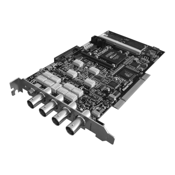
About Your ATS660 Thank you for your purchase of an ATS660. The ATS660 PCI based waveform digitizer has the following features: • Two 16-bit resolution analog input channels • Real-time sampling rate of 125 MS/s to 1 KS/s • 8 Million samples of onboard memory per channel, standard •... -
Page 11: Acquiring Data With Your Ats660
Acquiring Data with Your ATS660 You can acquire data either programmatically by writing an application for your ATS660 or interactively with the API Panel software. If you want to integrate the ATS660 in your test and measurement or embedded OEM application, you can program the digitizer using C/C++, Visual BASIC or LabVIEW for Win32 (Windows 98SE, Windows 2000 and Windows XP) operating systems or C for Linux operating systems. -
Page 12: Interactively Controlling Your Ats660 With Api Panel
ATS660 as you would a desktop oscilloscope. To launch the Scope Soft Front Panel, select Start » Programs » AlazarTech » API Panel The following screen will be displayed. If you connect the input to a signal generator and click on Start button, you should see the signal on the screen. -
Page 13: Ats-Sdk Api
ATS-SDK API The ATS-SDK API is used for programming the ATS660 in C/C++ or Visual BASIC. It provides the exact same API that is used for writing API Panel software. To help you get started, ATS-SDK comes with examples you can use or modify. -
Page 14: Ats-Linux For Ats660
ATS-Linux for ATS660 The ATS-Linux for ATS660 can be used for programming the ATS660 under Linux operating system. A binary driver is supplied that has been compiled for Kernel 2.6 running on an i386 platform. Sample program is supplied in C. The API is identical to the Windows API. -
Page 15: Optional Upgrades
Optional Upgrades AlazarTech offers the following upgrades and accessories for use with your ATS660 digitizer: • ATS660: External Clock Upgrade • ATS660: Master/Slave SyncBoard 2 position • ATS660: Master/Slave SyncBoard 4 position • ATS660: Master/Slave SyncBoard 8 position • ATS660: 8M to 128M Memory Upgrade... -
Page 16: Chapter 2 - Installation And Configuration
Chapter 2 - Installation and Configuration This chapter describes how to unpack, install, and configure your ATS660. ATS660 User Manual... -
Page 17: What You Need To Get Started
What You Need to Get Started To set up and use your ATS660, you will need the following: • One or more ATS660 digitizers • ATS660 Install Disk • For Master/Slave operation only: SyncBoard of appropriate width SyncBoard 2X for up to 2 digitizers ATS660 User Manual... - Page 18 SyncBoard 4X for up to 4 digitizers SyncBoard 8X for up to 8 digitizers ATS660 User Manual...
-
Page 19: Unpacking
• Remove the digitizer from the package and inspect the digitizer for loose components or any other sign of damage. Notify AlazarTech if the digitizer appears damaged in any way. Do not install a damaged digitizer into your computer. •... -
Page 20: Installing The Ats660
Installing the ATS660 There are four main steps involved in installation: 1. Physically install the digitizer(s) and SyncBoard, if any, in your computer 2. Install ATS660 software driver, when prompted by the operating system 3. Install API Panel software that allows you to setup the hardware, acquire signals and view and archive them 4. - Page 21 1. Physically install the digitizer in your computer Make sure that your computer is powered off before you attempt to insert the ATS660 digitizer in one of the free PCI slots. For best noise performance, leave as much room as possible between your ATS660 and other hardware.
- Page 22 For Master/Slave Installation If you are installing multiple ATS660 digitizers that will be configured as a Master/Slave system, make sure that you insert all cards in adjacent slots. The connector on the SyncBoard that is labeled as “M” (Master), must be inserted into the Master/Slave connector of the left-most digitizer, if you are facing the BNC connectors of the ATS660 digitizers.
- Page 23 If you are installing fewer than the maximum number of digitizers supported by your SyncBoard, the unused SyncBoard connectors must be on the right- hand side of the digitizers, if you are facing the BNC connectors of the ATS660 digitizers. Once you have completed this step, you should power the computer on.
- Page 24 2. Install ATS660 software driver, when prompted The following instructions guide you through the process of installing the ATS660 in a computer running Windows XP, Windows 2000 or Windows 98SE operating systems. Other operating systems, such as Windows NT, are not covered here. Installation of Multiple ATS660 Digitizers If you are installing multiple ATS660 digitizers, the operating system will detect one card at a time and...
- Page 25 Installing ATS660 Driver In Windows 98SE When you first plug in an ATS660 digitizer into a computer, the plug-n-play Windows 98SE operating system will detect the presence of a new PCI card and ask you to provide the device driver. a) Operating System will display the Welcome to the Found New Hardware Wizard Click Next.
- Page 26 Operating system will display the Select a Device Driver dialog box again. Make sure the AlazarTech ATS660 PCI Digitizer is selected. Then click Next. g) Operating system will display the Update Driver Warning. This warning is meant to tell you that Windows does not recognize the hardware.
- Page 27 Installing ATS660 Driver in Windows 2000 Before proceeding, make sure that you have sufficient administrative rights to install device drivers on your computer. Typically, you should be the Administrator for the computer you are installing device drivers on. When you first plug in an ATS660 digitizer into a computer, the plug-n-play Windows 2000 operating system will detect the presence of a new PCI card and ask you to provide the device driver.
- Page 28 Operating system will display the Select a Device Driver dialog box again. Make sure the AlazarTech ATS660 PCI Digitizer is selected. Then click Next. h) Operating system will display the Update Driver Warning. This warning is meant to tell you that Windows does not recognize the hardware.
- Page 29 Installing ATS660 Driver In Windows XP Before proceeding, make sure that you have sufficient administrative rights to install device drivers on your computer. Typically, you should be the Administrator for the computer you are installing device drivers on. When you first plug in an ATS660 digitizer into a computer, the plug-n-play Windows XP operating system will detect the presence of a new PCI card and ask you to provide the device driver.
- Page 30 Click OK. Operating system will display the Select the device driver you want to install for this hardware dialog box again. Make sure the AlazarTech ATS660 PCI Digitizer is selected (highlighted). Click Next. g) Operating system will display the Update Driver Warning.
- Page 31 Panel folder on the ATS660 Install Disk. Run Setup.exe program • Follow the instructions on the screen. If you are installing API Panel after having downloaded the installation file from AlazarTech web site: • Download API Panel installation file from www.alazartech.com/support/downloads.htm •...
- Page 32 4. Optionally, install the ATS-SDK software development kit or ATS-VI LabVIEW VI, which enables you to programmatically control the ATS660 Insert the ATS-SDK or ATS-VI CD. Software installation will start automatically. If, for any reason, installation does not start automatically, run the SETUP.EXE program. Follow the instructions on the screen.
-
Page 33: Installing The Ats660 In A Linux System
Installing the ATS660 in a Linux System ATS660 is fully compatible with the popular Linux operating system. AlazarTech supplies binary Linux drivers that have been compiled for Fedora Core 4 (kernel 2.6). Customers who require drivers for another version of Linux must contact the factory to obtain source code for the drivers (requires a Non-Disclosure Agreement). -
Page 34: Compiling The Ats660 Linux Driver
The customer should be able to run the AlazarDSO application or Acq2Disk sample in /usr/local/AlazarTech/samples/ATS660. 6. If it is necessary to rebuild the library, type cd PlxLinux/linux/api make This will create SharedLibrary/libPlxApi.so.0.0. Copy the file to /usr/local/AlazarTech/lib and then run ldconf ATS660 User Manual... -
Page 35: Configuring Internet Security And Virus Protection Software To Allow Proper Operation Of Ats Class Digitizers
PCI devices that have not been assigned to a software application by the user. Users of AlazarTech PCI digitizers must configure their security software to allow access to the PCI digitizers. - Page 36 Make sure AlazarTech hardware and software are fully functional • Re-install Norton Anti-Virus software AlazarTech PCI digitizer products are fully compatible with all internet security and anti-virus software. Users must make sure that their security software has been updated and configured properly..
-
Page 37: Updating Ats660 Driver
Updating ATS660 Driver From time to time, AlazarTech updates the device drivers for its products. These updates may be required for product enhancements or for bug fixes. This section of the manual takes you through the steps required to update the device driver for the ATS660 PCI digitizer. - Page 38 9. To complete the installation, follow the instructions provided in the section labeled: a. Installing ATS660 Driver in Windows 98SE b. Installing ATS660 Driver in Windows 2000 c. Installing ATS660 Driver in Windows XP ATS660 User Manual...
-
Page 39: Chapter 3 - Hardware Overview
Chapter 3 - Hardware Overview This chapter includes an overview of the ATS660, explains the operation of each functional unit making up your ATS660, and describes the signal connections. Following is a high- level block diagram of ATS660. CH A Analog Front-End ASoPC... -
Page 40: Input Connectors
Input Connectors ATS660 digitizers have one SMA connector for ECLK (External Clock) Input, two standard BNC female connectors for CH A and CH B analog input connections, one standard BNC female connector for the TRIG IN (External Trigger) input and one standard BNC female connector for AUX I/O (Auxiliary Input or Output). -
Page 41: Signal Connections
Signal Connections You can use CH A and CH B to digitize data as well as to trigger an acquisition. Use the EXT input for an external analog trigger only; data on the TRIG channel cannot be digitized. If External Clock Upgrade is installed on your ATS660, use the ECLK input for clocking the ATS660 in applications that require an external clock. -
Page 42: Analog Input
Analog Input The two analog input channels are referenced to common ground in bipolar mode. These settings are fixed; therefore, neither the reference nor the polarity of input channels can be changed. You cannot use CH A or CH B to make differential measurements or measure floating signals unless you subtract the digital waveforms in software. -
Page 43: Pipelined Adc
Pipelined ADC Each of the two ADCs on the ATS660 is a pipelined flash converter with a maximum conversion rate of 130 MS/s. If you use an external clock, you must provide a free-running clock to ensure reliable operation. You also must follow all the timing specifications on the external clock as described in Appendix A, Specifications. -
Page 44: Specifying Pretrigger Depth
Specifying Pretrigger Depth ATS660 acquires a certain number of samples, called the pretrigger depth, before it allows the trigger circuitry to operate, thereby guaranteeing that the required number of sample points will be captured before trigger occurs. User is allowed to set pretrigger depth for an acquisition session. -
Page 45: Amplifier Bypass Option
Amplifier Bypass Option ATS660 includes the capability to bypass the input amplifier in order to maximize dynamic performance. ATS660 allows the user to set and reset the Amplifier Bypass Option using on-board DIP switches. The user can bypass the amplifier on any one, or both, channels of ATS660. - Page 46 The concept behind Amplifier Bypass Option is very simple, as shown below: NEAR SWITCH SWITCH VARIABLE GAIN INPUT AMPLIFIER (INCLUDES ATTENUATORS) There are two DIP switches per channel: the one closest to the input BNC connectors is called the “Near Switch” and the one closest to the ADC IC is called the “Far Switch”.
- Page 47 The default setting of all four of the DIP switches is shown below: The black square represents the plastic tab for the switch. Note that the actual tab may not be black. It may, in fact, be white. ATS660 User Manual...
- Page 48 To set Amplifier Bypass Option for a channel, change the DIP Switch setting of the Near and Far switches for that particular channel to be as shown below: To re-insert the input amplifier in the signal path, i.e. to remove Amplifier Bypass Option, change the DIP Switch setting of the Near and Far switches for that particular channel to be the same as the factory-set default: NOTE THAT ANY SETTINGS OTHER THAN THE ONES...
-
Page 49: Calibration
Calibration is the process of minimizing measurement errors by making small circuit adjustments. All ATS660 digitizers come factory calibrated to the levels indicated in Appendix A, Specifications. Note that AlazarTech calibration is fully NIST traceable. However, your digitizer needs to be periodically recalibrated in order to maintain its specified accuracy. -
Page 50: Master/Slave Operation
Master/Slave Operation You can use two or more ATS660 digitizers in one system to increase the number of channels for your application by synchronizing digitizers using the appropriate SyncBoard. Currently, up to 16 channel (8 board) systems are supported for ATS660. For higher channel counts, contact the factory for special system configuration. -
Page 51: Restrictions
Restrictions To ensure proper master/slave operation of your ATS660 digitizers, you must observe the following restrictions: • All Master/Slave digitizers must be installed in adjacent slots, i.e. there should be no gap between the digitizers that are to be configured as a Master/Slave system Good Installation Bad Installation... - Page 52 The presence of a SyncBoard is detected by the ATS660 driver when the ATSApi DLL is loaded. This DLL gets loaded when you run any application program written for ATS660. Examples of such application programs are API Panel, one of the sample programs supplied with ATS-SDK or ATS-VI or any custom software written using ATS-SDK or ATS-VI.
-
Page 53: Hyperdisp ® Display Technology
® HyperDisP Display Technology ® ATS660 uses proprietary HyperDisP technology to allow the user to display datasets as long as 128 Million points in a few seconds. This provides the user with instantaneous feedback on the screen, compared to many tens of seconds or even minutes it may take with other product on the market. -
Page 54: Optional External Clock
Optional External Clock ATS660 PCI Digitizer optionally allows you to supply the ADC clock. This option is extremely important in many RF applications in which phase measurements must be made between the inputs themselves or between the inputs and an external event. -
Page 55: Fast External Clock
Fast External Clock This setting must be used when the external clock frequency is in the range of 1 MHz to 125 MHz. The frequency can change from one cycle to the next, as long as it stays within this range. It is highly recommended that the external clock signal have a duty cycle of 50% +/- 5%. -
Page 56: Optional Dual-Port Memory & Autodma
Optional Dual-Port Memory & AutoDMA One of the most unique features of the ATS660 is its dual- port memory and the associated AutoDMA mechanism of transferring data to host PC memory without any appreciable “in-process” software involvement. These features are particularly useful for applications that require: a) Continuous, gapless data capture. -
Page 57: Real-Time Operating Systems
Frequency (PRF) of 1 KHz or so, even though each capture is only 2048 bytes (requiring a throughput of only 2 MB/s). In other words, digitizers that specify raw data throughput of 100 MB/s can hardly handle 2MB/s effective throughput due to the operating system related delays in issuing re-arm commands. -
Page 58: Dual Port Memory
A PCI digitizer being used in a PRF application is, by definition, doing “burst DMA for lengthy period”, and is a type of product that can negatively impact response times of the RTOS. As such, the claim that an RTOS can remove all timing uncertainties in PRF application is suspect, to say the least. -
Page 59: Autodma For Prf Captures And Streaming Applications
Or in the case of continuous capture, or Data Streaming, ATS660 acquires a specific number of samples, say 1 Megasample, and initiates a DMA while capturing the next Megasample of data, thereby guaranteeing that there is no break in data storage. In both cases, the system does not have to wait until the end of data capture to read the acquired data. - Page 60 For streaming applications, PCI Transfer Rate is equal to the sample rate set by the user. An ATS660-8M transferring across the bus at 5 MS/s (10 MB/s) provides latency protection of (8MS / 5MS/s) = 1.6 seconds. This is usually sufficient for most Windows related latencies, including disk accesses, screen updates etc.
-
Page 61: Chapter 4 - Using Api Panel Software
You can launch API Panel by the following two methods: 1. By double-clicking on the API Panel desktop icon 2. By running Start » Programs » AlazarTech » API Panel You will hear the clicking of some on-board relays, as API Panel initializes the hardware and places it in a known state. - Page 62 API Panel screen is divided into five sections: 1. Data Display Area 2. Hardware Control Area 3. Display Control Area 4. Information Area 5. Menu Area Information Area Data Display Area Menu Area Display Control Area Hardware Control Area ATS660 User Manual...
- Page 63 Data Display Area is an oscilloscope style grid of 8 vertical and 10 horizontal divisions. By default, all signals are overlapped, with the zero-level being the vertical mid-point of the area. Hardware Control Area provides the user complete control over the hardware parameters of the ATS660. API Panel also performs complete error checking on all user selections to make sure that only valid settings are passed on to the hardware.
- Page 64 Channel A Input Control API Panel allows the user to set the vertical scale, input coupling and input impedance for Channel A. Note that the full-scale input range is defined as being +/- 4 divisions. Therefore, a vertical scale of 250 mV/div results in full scale input range of +/- 1V.
- Page 65 Multiple Record captures as well as Single Record captures: In Auto-Trigger mode, the trigger system generates a software trigger after waiting a pre-determined amount of time. In Multiple Record captures, each record can generate its own timeout. This mode is usually employed during the part of experimentation in which you are not aware of what exact signals you are trying to capture.
- Page 66 • Record length must not exceed 8,000,000 points for the 8M model or 128,000,000 points for the 128M model • Record length must be a multiple of 64 points • Pre-Trigger Depth must not exceed (Record Length – 64) • Number of Records to Capture must not exceed the lower of 256,000 or (8,000,000 / (Record Length + 16)) or for the 8M version...
- Page 67 Display Control Area allows the user to select the View Record and the display timebase. It also displays the 40-bit timestamp for the record selected. This area also includes the Start, Stop and Force Trigger command buttons. A Trigger indicator is also included in this area. The user is not allowed to set View Record to be greater than the number of records captured.
- Page 68 Information Area displays all the AlazarTech systems installed on the computer. This information is displayed in an Explorer-like tree structure. By expanding any System, users can check how many digitizers are included in the system and whether they are ATS660 or another type of digitizer.
- Page 69 Menu Area provides the standard Windows menus. File menu allows the user to save acquired signals as comma separated ASCII values or FlexPro compatible ASCII files. Select Exit command from the file menu to terminate API Panel. Preferences menu allows the user to select whether the individual points should be displayed as circles or they should be connected by a straight line.
-
Page 70: Appendix A - Specifications
Appendix A - Specifications This appendix lists the specifications of the ATS660. These specifications are typical at 25 °C unless otherwise stated. The operating temperature range is 0 to 50 °C. System Requirements Pentium based computer with at least one free PCI slot, 128 MB RAM, 20 MB of free hard disk space, SVGA display adaptor and monitor with at least an 800 x 600 resolution. - Page 71 Acquisition System Resolution 16 bits Bandwidth (-3dB) DC-coupled, 1MΩ DC - 65 MHz DC-coupled, 50Ω DC - 65 MHz AC-coupled, 1MΩ 10 Hz - 65 MHz AC-coupled, 50Ω 100KHz - 65 MHz Bandwidth flatness: ± 1dB, from DC to 10 MHz with DC coupling ±...
- Page 72 Acquisition Memory System Acquisition Memory/channel For ATS660-8M: Up to 8,000,000 samples per channel standard For ATS660-128M: Up to 128,000,000 samples per channel standard Record Length Software selectable with 16-point resolution. Record length must be a minimum of 128 points. Maximum record length is limited by the acquisition memory per channel.
- Page 73 Optional ECLK (External Clock) Input Signal Level LVTTL levels or 200 mV sine wave Input impedance 50Ω Input Coupling AC or DC, software selectable Maximum frequency Fast External Clock: 125 MHz with 50% ±5% duty cycle Slow External Clock: 10 MHz with minimum positive or negative pulse width of 10 ns 10 MHz Clock Reference: 10.5 MHz...
- Page 74 Bandwidth 65 MHz Trigger Delay Software selectable from 0 to 9,999,999 sampling clock cycles Trigger Timeout Software selectable with a 10 us resolution. Maximum settable value is 3,600 seconds. Can also be disabled to wait indefinitely for a trigger event EXT (External Trigger) Input Input impedance 1 MΩ...
- Page 76 ALAZAR TECHNOLOGIES INC. 3551 St-Charles, Unit 640 Kirkland, QC CANADA H9H 3C4 Tel: (514) 633-0001 Fax: (514) 633-0021 E-mail: info@alazartech.com Web: www.alazartech.com www.pci-digitizers.com...
Need help?
Do you have a question about the PCI Digitizers ATS660 and is the answer not in the manual?
Questions and answers