Table of Contents
Advertisement
Quick Links
Advertisement
Table of Contents

Summary of Contents for SINO Lokshun KA800M
- Page 1 KA800M Magnetic Scale Operation Instructions GUANGZHOU SINO DRO CO., LTD...
-
Page 2: Table Of Contents
Contents Safety Precautions....................1 Applications ........................1 Precautions ........................1 Validity ..........................1 Features and Specifications..................2 Principle of Operation ..................2 Structure ........................3 Installation ......................4 Priority of installation: ....................Fine reference installation ..................... Coarse reference installation ..................Signal Cables .......................12 Troubleshooting....................12... -
Page 3: Safety Precautions
KA800M Magnetic Scale Safety Precautions This manual is designed for technicians concerning installation and commissioning. Please read this manual carefully before use. Unauthorized modification and operation will invalidate the warranty. 1.1 Applications KA800M Magnetic Scale is a linear displacement sensor designed with a theoretical measuring length of up to 100m. -
Page 4: Features And Specifications
KA800M Magnetic Scale Features and Specifications KA800M magnetic scale is a non-contact displacement measurement system, using detection of magnetic signals, which features: High precision of up to ± 10µm / 300mm or ± 20µm / 1000mm, Measurement length of up to 3–100m, Low sensitivity to impact, vibration and contamination (e.g. -
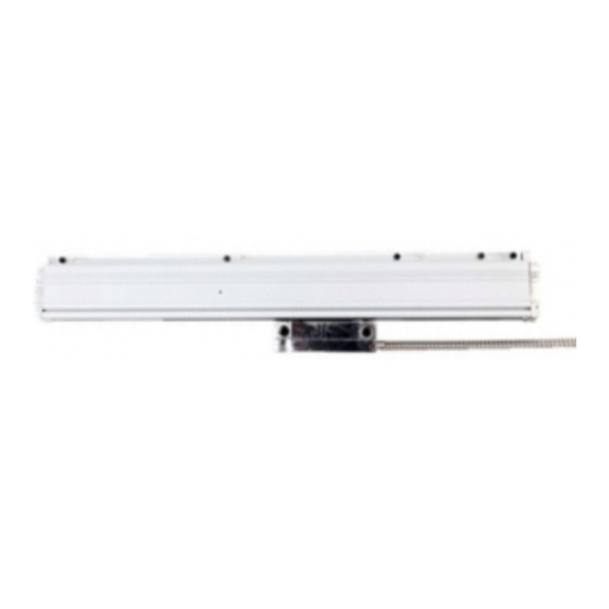
Page 5: Structure
KA800M Magnetic Scale Structure KA800M magnetic scale mainly consists of the body and the reading head. The body consists of the head section, the standard section and the end section (Fig. 4.1). Only one head and end sections are provided, and the quantity of standard sections may vary as the measuring length changes. -
Page 6: Installation
KA800M Magnetic Scale Installation 5.1 Priority of installation: (1) To install the magnetic scale, the scale shall be kept parallel with the lathe guide rail. (2) The center of the measuring range of magnetic scale shall be located at the center of the lathe travel. -
Page 7: Fine Reference Installation
KA800M Magnetic Scale Installation 5.2 Fine reference installation Steps of installation: (1) Machining reference face: Select a suitable place for installation and installation reference face. The installation reference face shall be machined to a roughness of Ra6.3. Drill M6 screw holes on the installation reference face with intervals and dimensions as shown in Fig. - Page 8 KA800M Magnetic Scale Installation (4) Attachment of tape: Remove the backing as shown in Fig. 5.6, and attach the tape straight on the specified position on the steel strip by clamping the tape with a jig. (Figs. 5.6 and 5.7) Sticker Tape Stainless...
- Page 9 KA800M Magnetic Scale Installation (6) Installation of read head: Put the sealing strip through the Ф4 hole, with the toothed edge upwards (Fig. 5.8). Install the connection base symmetrically on both sides of the read head, with the base closely placed to the both contact face as shown in Fig. 5.9. Fix the read head to the scale casing with a jig as shown in Figs.
- Page 10 KA800M Magnetic Scale Installation Signal cable Fig. 5.12 Cable direction reversion Connect and fix the read head to the moving part of the lathe. General accessories provided include: T-support A, B, C, D, and E, which are optional and used as a transition part for connection between the read head and moving part of the lathe.
-
Page 11: Coarse Reference Installation
KA800M Magnetic Scale Installation Putting through the Sealing strip round hole Cylindrical pin Fig. 5.13 Installation of sealing strip Fig. 5.14 Installation of body cover Application of sealant Self-tapping screw Fig. 5.15 Installation of strip Fig. 5.16 Application of sealant 5.3 Coarse reference installation Brackets are options specially designed for coarse reference installation. - Page 12 KA800M Magnetic Scale Installation Adjusting screw Fixing screw M5 X 16 M6 X 20 Adjusting screw M5 X 16 Scale casing installation hole M5 Vertically <0.1mm Adjusting screw Horizontally M5 X 16 <0.1mm Fig. 5.17 Installation method for bracket adjustment Unit: mm Full length of magnetic scale=L0+214 Locations of scale casing connection...
- Page 13 KA800M Magnetic Scale Installation If 700≤X≤1800, X=L and n=0. e.g. if the effective measuring length L of the magnetic scale is 9000mm X=L0-2240=9000-2240=6760 X=6760≥1900, L= X-n×1200, 700≤L≤1800 ∵ L=6760 -n×1200, 700≤L≤1800 , L=760mm ∴ The quantity of brackets is n+4=9. Steps of coarse reference installation: (1) Installation of bracket: Drill M6 screw holes to install a bracket.
-
Page 14: Signal Cables
KA800M Magnetic Scale Signal Cables (1) Pinout: See Table 6.1. Table 6.1 Pinout Pin No. Signal Idle Green Orange White / Color Black Green Orange White /Black / Black Black (2) Length of cable The length of standard cable is 5m. Troubleshooting Failure Cause... - Page 15 GUANGZHOU SINO DRO CO., LTD http://www.sino-ld.com Service on-line:02081639851...
Need help?
Do you have a question about the Lokshun KA800M and is the answer not in the manual?
Questions and answers