Table of Contents
Advertisement
Quick Links
Advertisement
Table of Contents

Summary of Contents for Postek MX Series
- Page 2 Microsoft, Windows are registered trademarks of Microsoft Corporation. Copyright © 2023 by Postek Electronics Co., Ltd. All rights reserved. Under the copyright laws, this manual cannot be reproduced in any form without the prior written permission of POSTEK. No patent liability is assumed, with respect to the use of the information contained herein.
- Page 3 (according to POSTEK Warranty Clauses) only. In no event shall POSTEK or the resellers involved be liable for any direct or indirect loss, including but not limited to loss of business profits, business interruption, loss of business information, or other pecuniary loss.
-
Page 4: Table Of Contents
MX Series Industrial Print Engine User’s Manual Contents Contents Preface .......................... 1 Important Notes ......................2 Chapter 1: Introduction ....................4 1.1 Specifications ......................... 4 1.2 Contents in the Box ........................ 6 Chapter 2: Setup and Use ................... 7 2.1 Main Parts and Structures ...................... 7 2.1.1 Front View ........................ - Page 5 MX Series Industrial Print Engine User’s Manual Contents Appendix A: Interface Specifications ..............100 Appendix B: ASCII Table ..................104...
-
Page 6: Preface
This manual explains how to set up and begin using your printer. It also provides detailed information on configuring your printer, basic operations, care, and troubleshooting. Please read this manual carefully before using the POSTEK printer. Symbol Conventions The symbols that may be found in this document are defined as follows. -
Page 7: Important Notes
MX Series Industrial Print Engine User’s Manual Important Notes Important Notes Please read the following passages thoroughly before proceeding. Printhead The thermal printhead can be easily damaged due to its precision construction. A printhead damaged by misuse is not covered under the terms of the warranty. To ensure longevity of the printhead, please note the following: DO NOT scrape or use tools that might damage the printhead surface. - Page 8 MX Series Industrial Print Engine User’s Manual Important Notes Cutter (Optional) The printer equipped with a cutter can automatically cut the label after printing. However, automatic cutters pose a safety hazard since the blades are very sharp. To prevent injuries and cutter failures...
-
Page 9: Chapter 1: Introduction
MX Series Industrial Print Engine User’s Manual Chapter 1: Introduction Chapter 1: Introduction 1.1 Specifications Model MX2/MX2 Pro MX3/MX3 Pro MX6/MX6 Pro Model with RFID MX2r/MX2r Pro MX3r/MX3r Pro MX6r/MX6r Pro Printing Mode Direct Thermal Direct Thermal and Thermal Transfer Max Print Speed 18 ips (457.2 mm/s) - Page 10 Storage Environment Relative humidity: 5% ~ 90% non condensing ①: HEAT , or Heating Equilibrium Adaptive Tuning, is a POSTEK designed and developed cutting-edge technology that sets the benchmark for heat management in thermal printing. Printers equipped with HEAT have significant improvements in their printout clarity and print speed. The HEAT level represents the fineness of the heating uniformity with level I being the finest.
-
Page 11: Contents In The Box
MX Series Industrial Print Engine User’s Manual Chapter 1: Introduction Optional Features RFID Verifier* External-mount module (Only available for RFID models) There are three software packages listed below for the visual verifier, and users can choose one from them based on needs and budget: 1. -
Page 12: Chapter 2: Setup And Use
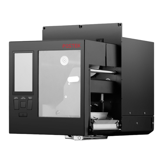
2.1 Main Parts and Structures The MX series comprises two types of printer models, the Standard MX and the MX Pro. In addition to the features of the Standard MX model, the MX Pro model offers a much larger main frame that incorporates the media supply and liner rewinding mechanism. - Page 13 MX Series Industrial Print Engine User’s Manual Chapter 2: Setup and Use Figure 2-2 shows the front view of the MX Pro. Figure 2-2 Front View (MX Pro) Table 2-2 Front View Description Number Description Media Spindle Stop Plate_Media Spindle...
-
Page 14: Interior View
MX Series Industrial Print Engine User’s Manual Chapter 2: Setup and Use 2.1.2 Interior View Figure 2-3 shows the interior view of the Standard MX. Figure 2-3 Interior View (Standard MX) Table 2-3 Interior View Description Number Description Stop Plate_Ribbon Supply Spindle... - Page 15 MX Series Industrial Print Engine User’s Manual Chapter 2: Setup and Use Figure 2-4 shows the interior view of the MX Pro. Figure 2-4 Interior View (MX Pro) Table 2-4 Interior View Description Number Description Stop Plate_Ribbon Supply Spindle Stop Plate_Ribbon Take-up Spindle...
-
Page 16: Rear View
MX Series Industrial Print Engine User’s Manual Chapter 2: Setup and Use 2.1.3 Rear View The printer is equipped with multiple interfaces. Figure 2-5 shows the rear view of the Standard MX. Figure 2-5 Rear View (Standard MX) Table 2-5 Rear View Description... - Page 17 MX Series Industrial Print Engine User’s Manual Chapter 2: Setup and Use Figure 2-6 shows the rear view of the MX Pro. Figure 2-6 Rear View (MX Pro) Table 2-6 Rear View Description Number Description RS-232 Serial Port USB Host...
-
Page 18: Consumables Loading Path
MX Series Industrial Print Engine User’s Manual Chapter 2: Setup and Use 2.1.4 Consumables Loading Path Figure 2-7 shows the consumables’ loading paths in Tear-off mode of the Standard MX. Figure 2-7 Loading Paths in Tear-off Mode (Standard MX) Table 2-7 Loading Path Description... - Page 19 MX Series Industrial Print Engine User’s Manual Chapter 2: Setup and Use Figure 2-8 shows the consumables’ loading paths in Tear-off mode of the MX Pro. Figure 2-8 Loading Paths in Tear-off Mode (MX Pro) Table 2-8 Loading Path Description...
- Page 20 MX Series Industrial Print Engine User’s Manual Chapter 2: Setup and Use Figure 2-9 shows the consumables’ loading paths in Peeler Mode of the Standard MX. Figure 2-9 Loading Paths in Peeler Mode (Standard MX) Table 2-9 Loading Path Description...
- Page 21 MX Series Industrial Print Engine User’s Manual Chapter 2: Setup and Use Figure 2-10 shows the consumables’ loading paths in Peeler Mode of the MX Pro. Figure 2-10 Loading Paths in Peeler Mode (MX Pro) Table 2-10 Loading Path Description...
-
Page 22: Setting Up The Printer
• • Connecting to a wrong power source may cause damage to your printer. POSTEK assumes no liability for any damage in such cases. The rating for the printer is 110/240 VAC ±10%, 50/60 1. Make sure the printer is switched OFF. - Page 23 MX Series Industrial Print Engine User’s Manual Chapter 2: Setup and Use Figure 2-12 Plug the Power Cord The shape of power plug varies depending on the region in which it was purchased.
-
Page 24: Loading The Ribbon
MX Series Industrial Print Engine User’s Manual Chapter 2: Setup and Use 2.2.3 Loading the Ribbon Load ribbon only when using the thermal transfer printing mode. Remove any ribbon that may be • loaded when using the direct thermal printing mode. - Page 25 MX Series Industrial Print Engine User’s Manual Chapter 2: Setup and Use 4. Place the ribbon roll on the Ribbon Supply Spindle, see Figure 2-15. Make sure that the ribbon roll is firmly pushed against the Stop Plate. Figure 2-15 Load Ribbon Roll 5.
- Page 26 MX Series Industrial Print Engine User’s Manual Chapter 2: Setup and Use Figure 2-17 Wrap Ribbon on the Core 7. Slide the Ribbon Take-up Roll on the Ribbon Take-up Spindle and push it firmly against the Stop Plate. Turn the Take-up Spindle until the ribbon is tightly wound. See Figure 2-18.
-
Page 27: Loading The Media
MX Series Industrial Print Engine User’s Manual Chapter 2: Setup and Use 2.2.4 Loading the Media • When it is the first time installing the media or when changing to a different type of media, media sensor calibration must be performed. - Page 28 MX Series Industrial Print Engine User’s Manual Chapter 2: Setup and Use 2.2.4.1 Switching Media Core Adapters The MX Pro is equipped with both 1.5″ and 3″ media core adapters. The 1.5″ core adapter is located inside the 3″ core adapter. To load a 1.5″ core media roll, please first remove the 3″ core adapter;...
- Page 29 MX Series Industrial Print Engine User’s Manual Chapter 2: Setup and Use 2.2.4.2 Tear-off Mode • Tear-off Mode is the default handling mode. • The media installation procedure in Standard Mode is the same as in Tear-off Mode. To load media into the printer while under Tear-off Mode, follow the steps below: 1.
- Page 30 MX Series Industrial Print Engine User’s Manual Chapter 2: Setup and Use Figure 2-21 Thread the Media 3. Slide the Media Guide to the edge of the media, and make sure not to pinch or squeeze the media; keep the media flat and smooth.
- Page 31 MX Series Industrial Print Engine User’s Manual Chapter 2: Setup and Use 6. Turn on the printer and wait for the printer to boot normally, then calibrate the media sensor. You can choose to calibrate the media sensor manually (press and hold the [FEED/Calibration] button for around 4 seconds) or automatically (refer to 3.2.1.5 Calibration &...
- Page 32 MX Series Industrial Print Engine User’s Manual Chapter 2: Setup and Use 2.2.4.3 Peeler Mode To load media into the printer while under Peeler Mode, follow the steps below: 1. Load a media roll onto the media spindle, please refer to step 1 in 2.2.4.2 Tear-off...
- Page 33 MX Series Industrial Print Engine User’s Manual Chapter 2: Setup and Use Figure 2-25 Lock the Printhead 6. Turn on the printer and wait for the printer to boot normally, then calibrate the media sensor. You can choose to calibrate the media sensor manually (press and hold the [FEED/Calibration] button for around 4 seconds) or automatically (refer to 3.2.1.5 Calibration &...
- Page 34 MX Series Industrial Print Engine User’s Manual Chapter 2: Setup and Use 8. Extend approximately 400 mm long media out of the printer. Peel off the face label(s) from the exposed media, leaving just the liner. As shown in Figure 2-27.
- Page 35 MX Series Industrial Print Engine User’s Manual Chapter 2: Setup and Use 10. Slide the Liner Take-up Roll on the Rewind spindle and push it firmly against the Stop Plate. Turn the Rewind spindle counter clockwise until the liner is tightly wound. See Figure 2-29.
- Page 36 MX Series Industrial Print Engine User’s Manual Chapter 2: Setup and Use Figure 2-31. Figure 2-31 Close the Flip-up Cover...
-
Page 37: Installing The Printer Driver
2.3 Installing the Printer Driver 2.3.1 USB Port Installation If you already have a POSTEK printer driver installed on your computer, the printer driver for the additional printer will be installed automatically. When installing the POSTEK printer driver for the first time, if you connect the printer to your computer via the USB port, please refer to the steps below to complete the printer driver installation (take Windows10 operating system as an example). - Page 38 MX Series Industrial Print Engine User’s Manual Chapter 2: Setup and Use Figure 2-33 Installation Directory Screen 5. On the “Installation Information” screen, check the box that says “Run Driver Wizard after unpacking drivers”, then click “Finish”, as shown in Figure 2-34.
- Page 39 MX Series Industrial Print Engine User’s Manual Chapter 2: Setup and Use Figure 2-35 Seagull Driver Wizard Screen 7. The connected printer will be detected, click “Next”, as shown in Figure 2-36. Figure 2-36 Printer Detected 8. On the “Specify Printer Name” screen, enter a name for the printer, as shown in Figure 2-37, then...
- Page 40 MX Series Industrial Print Engine User’s Manual Chapter 2: Setup and Use Figure 2-37 Specify Printer Name 9. Print a test page to see whether the printer is connected properly, as shown in Figure 2-38. Figure 2-38 Print Test Page...
-
Page 41: Network Port Installation
MX Series Industrial Print Engine User’s Manual Chapter 2: Setup and Use 2.3.2 Network Port Installation If you connect the printer to your computer via the Ethernet port, you will need to configure the printer's network parameters before installing the printer driver and configuring the printer’s port information. - Page 42 MX Series Industrial Print Engine User’s Manual Chapter 2: Setup and Use 2.3.2.2 Driver Installation and Port Configuration After the printer's network parameters have been configured, please refer to the following steps to complete the driver installation and port configuration.
- Page 43 MX Series Industrial Print Engine User’s Manual Chapter 2: Setup and Use Figure 2-41 Specify Printer Model Screen 5. On the “Specify Port” screen, click “Create Port…” to bring up “Create Port” dialog box, select “Standard TCP/IP Port” - “New Port…”, as shown in Figure 2-42.
- Page 44 MX Series Industrial Print Engine User’s Manual Chapter 2: Setup and Use Figure 2-43 Add Standard TCP/IP Printer Port Wizard 7. On the “Add Port” screen, enter the IP Address of the printer (Note: the IP address here must be consistent with the IP address of the printer that has been set, and the port name will be generated automatically), and then click “Next”, as shown in Figure 2-44.
- Page 45 MX Series Industrial Print Engine User’s Manual Chapter 2: Setup and Use Figure 2-45 Complete adding Standard TCP/IP Printer Port 9. Return to the “Specify Port” screen, select the TCP/IP Port that has been added, and click “Next”, as shown in Figure 2-46.
- Page 46 MX Series Industrial Print Engine User’s Manual Chapter 2: Setup and Use Figure 2-47 Specify Printer Name 11. Print a test page to see whether the printer is connected properly. As shown in Figure 2-48. Figure 2-48 Print Test Page...
-
Page 47: Installing Label Editing Software
2.4 Installing Label Editing Software Each printer also comes with a BarTender UltraLite edition software. To access to the software and the directions for use, please scan the QR code on the Quick Start Guide or visit POSTEK website: http://www.postekchina.com. -
Page 48: Chapter 3: Operations And Settings
MX Series Industrial Print Engine User’s Manual Chapter 3: Operations and Settings Chapter 3: Operations and Settings 3.1 The Front Panel The Front Panel of the printer consists of: Three multi-function buttons: [PAUSE/Self Test], [FEED/Calibration], and [CANCEL/Reset] • One status indicator •... -
Page 49: Panel Buttons
MX Series Industrial Print Engine User’s Manual Chapter 3: Operations and Settings 3.1.1 Panel Buttons The three buttons have different functions based on the mode of the operation is performed, please refer to Table 3-1 for details. Table 3-1 Panel Button Description... -
Page 50: Lcd Touchscreen
MX Series Industrial Print Engine User’s Manual Chapter 3: Operations and Settings 3.1.3 LCD Touchscreen The front panel of the printer contains a 4.5″ LCD capacitive touchscreen. Settings can be easily configured on the touchscreen. The main screen is shown in Figure 3-2. -
Page 51: Settings
MX Series Industrial Print Engine User’s Manual Chapter 3: Operations and Settings 3.2 Settings 3.2.1 General Settings 3.2.1.1 Darkness On the LCD touchscreen, select ″Settings″ > ″General″ > ″Darkness″ to enter the Darkness menu, as shown in Figure 3-3. Figure 3-3 Darkness Menu Set the print darkness from this menu. - Page 52 MX Series Industrial Print Engine User’s Manual Chapter 3: Operations and Settings Figure 3-4 Speed Menu Set the print speed and backfeed speed from this menu. Speed unit: ips (inches per speed). Print speed: Set the print speed. (Note: Slower print speed typically yields better print quality.) The print speed defaults to the value sent by print command or printer driver, if you want to use the menu settings, please uncheck the box ″Use the value sent by print...
- Page 53 MX Series Industrial Print Engine User’s Manual Chapter 3: Operations and Settings Note: Different print speeds may result in differences in printing results, so please use this function according to your actual needs. Backfeed speed: Set the backfeed speed of the label, i.e., the speed at which the label back feed from the tear-off/peeling/cutting position to the print position.
- Page 54 MX Series Industrial Print Engine User’s Manual Chapter 3: Operations and Settings 3.2.1.4 Print Mode On the LCD touchscreen, select ″Settings″ > ″General″ > ″Print Mode″ to enter the Print Mode menu, as shown in Figure 3-6. Figure 3-6 Print Mode Menu Set the print mode from this menu.
- Page 55 MX Series Industrial Print Engine User’s Manual Chapter 3: Operations and Settings 3.2.1.5 Calibration & Registration On the LCD touchscreen, select ″Settings″ > ″General″ > ″Calibration & Registration″ to enter the Calibration & Registration menu, as shown in Figure 3-7.
- Page 56 MX Series Industrial Print Engine User’s Manual Chapter 3: Operations and Settings 3.2.1.6 Print Direction On the LCD touchscreen, select ″Settings″ > ″General″ > ″Print Direction″ to enter the Print Direction menu, as shown in Figure 3-8. Figure 3-8 Print Direction Menu Set the print direction of the label content.
- Page 57 MX Series Industrial Print Engine User’s Manual Chapter 3: Operations and Settings 3.2.1.7 Printed Label Handling On the LCD touchscreen, select ″Settings″ > ″General″ > ″Printed Label Handling″ to enter the Printed Label Handling menu, as shown in Figure 3-9.
- Page 58 MX Series Industrial Print Engine User’s Manual Chapter 3: Operations and Settings Feeding direction Tearing edge Figure 3-12 Decrease Tear-off position Offset Diagram Accepted values: -1249.8 to 1249.8 mm (for 203dpi models) -847.3 to 847.3 mm (for 300dpi models) -423.6 to 423.6 mm (for 600dpi models) The Peeler Mode menu, as shown in Figure 3-12.
- Page 59 MX Series Industrial Print Engine User’s Manual Chapter 3: Operations and Settings Increase the value of this parameter will move the label’s trailing edge in the same direction as the media feeding direction, as shown in Figure 3-14. Feeding direction...
-
Page 60: Communication
MX Series Industrial Print Engine User’s Manual Chapter 3: Operations and Settings 3.2.2 Communication 3.2.2.1 Serial Port On the LCD touchscreen, select ″Settings″ > ″Communication″ > ″Serial Port″ to enter the Serial Port menu, as shown in Figure 3-16. Figure 3-16 Serial Port Menu Set the parameters of the serial port. - Page 61 MX Series Industrial Print Engine User’s Manual Chapter 3: Operations and Settings 3.2.2.2 Ethernet On the LCD touchscreen, select ″Settings″ > ″Communication″ > ″Ethernet″ to enter the Ethernet menu, as shown in Figure 3-17. Figure 3-17 Ethernet Menu Set the network port parameters.
- Page 62 MX Series Industrial Print Engine User’s Manual Chapter 3: Operations and Settings Figure 3-18 IPv4 Settings Menu Table 3-4 Description of IPv4 Setting Items Items Description Set to enable or disable the function of obtaining the printer IP address DHCP dynamically.
- Page 63 MX Series Industrial Print Engine User’s Manual Chapter 3: Operations and Settings 3.2.2.3 General I/O On the LCD touchscreen, select ″Settings″ > ″Communication″ > ″General I/O″ to enter the General I/O menu, as shown in Figure 3-19. Figure 3-19 General I/O Menu Set the input signal and output signal of the General I/O interface.
-
Page 64: Rfid
MX Series Industrial Print Engine User’s Manual Chapter 3: Operations and Settings 3.2.3 RFID 3.2.3.1 RFID Settings On the LCD touchscreen, select ″Settings″ > ″RFID″ to enable the RFID function, and then select ″RFID Settings″ to enter the RFID Settings menu, as shown in Figure 3-20. - Page 65 MX Series Industrial Print Engine User’s Manual Chapter 3: Operations and Settings Frequency Name Region Frequency Range New Zealand 922 ~ 928 Malaysia 919 ~ 923 Indonesia 923 ~ 925 Philippines 918 ~ 920 Taiwan, China 922 ~ 928 Macau, China...
- Page 66 MX Series Industrial Print Engine User’s Manual Chapter 3: Operations and Settings 3.2.3.2 Read RFID Tag Data On the LCD touchscreen, select ″Settings″ > ″RFID″ to enable the RFID function, and then select ″Read RFID Tag Data″ to enter the Read RFID Tag Data menu, as shown in Figure 3-22.
- Page 67 MX Series Industrial Print Engine User’s Manual Chapter 3: Operations and Settings 3.2.3.3 Calibration On the LCD touchscreen, select ″Settings″ > ″RFID″ to enable the RFID function, and then select ″Calibration″ to enter the Calibration menu, as shown in Figure 3-23.
-
Page 68: Management
MX Series Industrial Print Engine User’s Manual Chapter 3: Operations and Settings 3.2.4 Management 3.2.4.1 Preference On the LCD touchscreen, select ″Settings″ > ″Management″ > ″Preference″ to enter the Preference menu, as shown in Figure 3-24. Figure 3-24 Preference Menu Enable or disable the Automatic Adjustment of the Print Speed prompt message. - Page 69 MX Series Industrial Print Engine User’s Manual Chapter 3: Operations and Settings 3.2.4.2 Label Formats On the LCD touchscreen, select ″Settings″ > ″Management″ > ″Label Formats″ to enter the Label Formats menu, as shown in Figure 3-25. Figure 3-25 Label Formats Menu Under this menu, up to 100 label format files can be managed.
-
Page 70: Advanced
MX Series Industrial Print Engine User’s Manual Chapter 3: Operations and Settings 3.2.5 Advanced 3.2.5.1 Applicator Logic Control On the LCD touchscreen, select ″Settings″ > ″Advanced″ > ″Applicator Logic Control″ to enter the Applicator Logic Control menu, as shown in Figure 3-26. - Page 71 MX Series Industrial Print Engine User’s Manual Chapter 3: Operations and Settings The Single Air Cylinder Touch-on menu, see Figure 3-27. Figure 3-27 Single Air Cylinder Touch-on Menu Tamp position sensor: The tamp position sensor is a magnetic switch installed on one end (Single) or both ends (Double) of the air cylinder to detect the presence of the tamp.
- Page 72 MX Series Industrial Print Engine User’s Manual Chapter 3: Operations and Settings The Wipe-on menu, see Figure 3-28. Figure 3-28 Wipe-on Menu Product detect timeout: Set the maximum time to wait for the arrival of the package to be labeled after the label has been picked up by the tamp.
- Page 73 MX Series Industrial Print Engine User’s Manual Chapter 3: Operations and Settings 3.2.5.2 Label Position Offset On the LCD touchscreen, select ″Settings″ > ″Advanced″ > ″Label Position Offset″ to enter the Label Position Offset menu, as shown in Figure 3-29.
- Page 74 MX Series Industrial Print Engine User’s Manual Chapter 3: Operations and Settings 3.2.5.3 Horizontal Offset On the LCD touchscreen, select ″Settings″ > ″Advanced″ > ″Horizontal Offset″ to enter the Horizontal Offset menu, as shown in Figure 3-32. Figure 3-32 Horizontal Offset Menu parameter can be used to adjust the horizontal print position on a label.
- Page 75 MX Series Industrial Print Engine User’s Manual Chapter 3: Operations and Settings 3.2.5.4 Vertical Offset On the LCD touchscreen, select ″Settings″ > ″Advanced″ > ″Vertical Offset″ to enter the Vertical Offset menu, as shown in Figure 3-34. Figure 3-34 Vertical Offset Menu This parameter can be used to adjust the vertical print position on a label.
- Page 76 MX Series Industrial Print Engine User’s Manual Chapter 3: Operations and Settings 3.2.5.5 Registration Accuracy On the LCD touchscreen, select ″Settings″ > ″Advanced″ > ″Registration Accuracy″ to enter the Registration Accuracy menu, as shown in Figure 3-36. Figure 3-36 Registration Accuracy Menu Adjust the positioning accuracy of the backfeed label.
- Page 77 MX Series Industrial Print Engine User’s Manual Chapter 3: Operations and Settings Accepted values: -5.0 to 5.0 mm Default value: 0.6 mm (for 203dpi models) 0.4 mm (for 300dpi models) 0.2 mm (for 600dpi models) Use the detection data of: Set the label positioning to be based on the current label to print or the latest detected label.
- Page 78 MX Series Industrial Print Engine User’s Manual Chapter 3: Operations and Settings 3.2.5.6 Sensor Signal Strength On the LCD touchscreen, select ″Settings″ > ″Advanced″ > ″Sensor Signal Strength″ to enter the Sensor Signal Strength menu, as shown in Figure 3-39.
- Page 79 MX Series Industrial Print Engine User’s Manual Chapter 3: Operations and Settings 3.2.5.7 Reset On the LCD touchscreen, select ″Settings″ > ″Advanced″ > ″Reset″ to enter the Reset menu, as shown in Figure 3-40. Figure 3-40 Reset Menu Reset the printer from this menu.
- Page 80 MX Series Industrial Print Engine User’s Manual Chapter 3: Operations and Settings 3.2.5.8 Languages On the LCD touchscreen, select ″Settings″ > ″Advanced″ > ″Language″ to enter the Languages menu, as shown in Figure 3-41. Figure 3-41 Language Menu Set the language that the printer displays.
- Page 81 MX Series Industrial Print Engine User’s Manual Chapter 3: Operations and Settings 3.2.5.10 Date & Time On the LCD touchscreen, select ″Settings″ > ″Advanced″ > ″Date & Time″ to enter the Date & Time menu, as shown in Figure 3-43.
- Page 82 MX Series Industrial Print Engine User’s Manual Chapter 3: Operations and Settings 3.2.5.11 Maximum Feed Length On the LCD touchscreen, select ″Settings″ > ″Advanced″ > ″Maximum Feed Length″ to enter the Maximum Feed Length menu, as shown in Figure 3-44.
- Page 83 MX Series Industrial Print Engine User’s Manual Chapter 3: Operations and Settings 3.2.5.12 Media Feed Calibration On the LCD touchscreen, select ″Settings″ > ″Advanced″ > ″Media Feed Calibration″ to enter the Media Feed Calibration menu, as shown in Figure 3-45.
- Page 84 MX Series Industrial Print Engine User’s Manual Chapter 3: Operations and Settings 3.2.5.13 Media Roll Diameter On the LCD touchscreen, select ″Settings″ > ″Advanced″ > ″Media Roll Diameter″ to enter the Media Roll Diameter menu, as shown in Figure 3-46.
- Page 85 MX Series Industrial Print Engine User’s Manual Chapter 3: Operations and Settings ribbon roll into calculation, the system can determine how much ribbon remains on a ribbon roll. The default value of the diameter of the full ribbon roll is 2.5" (63.6 mm). If the full ribbon roll's real diameter is different from the default value, please modify it under this menu.
- Page 86 MX Series Industrial Print Engine User’s Manual Chapter 3: Operations and Settings 3.2.5.16 Firmware Update On the LCD touchscreen, select ″Settings″ > ″Advanced″ > ″Firmware Update″ to enter the Firmware Update menu, as shown in Figure 3-49. Figure 3-49 Firmware Update Menu Upgrade the printer firmware.
- Page 87 MX Series Industrial Print Engine User’s Manual Chapter 3: Operations and Settings 3.2.5.17 Dump Mode On the LCD touchscreen, select ″Settings″ > ″Advanced″ > ″Dump Mode″ to enter the Dump Mode menu, as shown in Figure 3-50. Figure 3-50 Dump Mode Menu Set the Dump Mode on or off.
- Page 88 MX Series Industrial Print Engine User’s Manual Chapter 3: Operations and Settings 3.2.5.19 About On the LCD touchscreen, select ″Settings″ > ″Advanced″ > ″About″ to enter the About page, as shown in Figure 3-53. Figure 3-53 About Page This menu allows you to view the device name, printer model, OX version, UI version, BSP version,...
-
Page 89: Mechanical Adjustments
MX Series Industrial Print Engine User’s Manual Chapter 3: Operations and Settings 3.3 Mechanical Adjustments 3.3.1 Adjusting the Media Sensor The printer’s Reflective and Transmissive integrated Media Sensor can be adjusted left and right, as shown in Figure 3-54. To adjust the Media Sensor: Move the Media Sensor Handle to adjust the media sensor to the appropriate position. - Page 90 MX Series Industrial Print Engine User’s Manual Chapter 3: Operations and Settings Tape Hole The tape shall avoid the hole area Tape Media gap The position of the tape should be made known to user to avoid positioning Media Sensors over the tape area.
-
Page 91: Adjusting The Printhead Pressure
MX Series Industrial Print Engine User’s Manual Chapter 3: Operations and Settings 3.3.2 Adjusting the Printhead Pressure A qualified technician is required to adjust the printhead pressure. Printhead damage or poor printout quality may occur if the procedure is not done correctly. - Page 92 MX Series Industrial Print Engine User’s Manual Chapter 3: Operations and Settings Bar to adjust, then slightly loosen the Pressure Bar by using the Allen wrench bundled with the printer. 2. Slide the Pressure Bar to an estimated position and fasten it with the Allen wrench.
-
Page 93: Adjusting The Ribbon Tension
MX Series Industrial Print Engine User’s Manual Chapter 3: Operations and Settings 3.3.3 Adjusting the Ribbon Tension Tension on both ribbon supply and ribbon take-up spindles can be adjusted, refer to Figure 3-57, by following the steps below. 1. Slightly loosen the Setscrew with the Allen wrench bundled with the printer. -
Page 94: Chapter 4: Maintenance
MX Series Industrial Print Engine User’s Manual Chapter 4: Maintenance Chapter 4: Maintenance • Make sure the printer is powered off before performing maintenance operations. • The Printhead may be hot due to recent printing. Wait until the Printhead cools before performing maintenance. -
Page 95: Cleaning The Sensors
MX Series Industrial Print Engine User’s Manual Chapter 4: Maintenance To clean the printer interior, use a cotton swabs dipped into anhydrous isopropyl alcohol and remove any dirt. 4.4 Cleaning the Sensors Over time, dust and debris will accumulate over the sensors and affect their performance, to ensure proper detection, please clean the sensors with cotton swabs dipped into anhydrous isopropyl alcohol periodically. -
Page 96: Chapter 5: Troubleshooting
MX Series Industrial Print Engine User’s Manual Chapter 5: Troubleshooting Chapter 5: Troubleshooting Occasionally situations occur that require some troubleshooting. Possible issues and potential solutions are listed in this section. While not every situation is addressed, you may find some of these tips useful. - Page 97 MX Series Industrial Print Engine User’s Manual Chapter 5: Troubleshooting Error Message Possible Cause Recommended Solution sensor failure. setting. Signal Strength″ to adjust the signal Error code: 11 strength. The sensor module is not installed or broken. Thermal transfer Only direct thermal printing printing not supported with this printer.
- Page 98 MX Series Industrial Print Engine User’s Manual Chapter 5: Troubleshooting Error Message Possible Cause Recommended Solution Error code:11004 please contact a qualified professional for service. Serial port error. Please restart the printer. If error remains, Error code:11005 please contact a qualified professional for service.
- Page 99 MX Series Industrial Print Engine User’s Manual Chapter 5: Troubleshooting Error Message Possible Cause Recommended Solution doesn’t match that in the Language″ to select the matching instructions sent to the printer programming language. Invalid command. Instructions sent to the printer Please check the command syntaxes.
- Page 100 MX Series Industrial Print Engine User’s Manual Chapter 5: Troubleshooting Error Message Possible Cause Recommended Solution Error code: 31002 Media detection Media sensor calibration not Press and hold the [FEED/Calibration] error. Error code: performed after replacing a button (hold for around 4 seconds) to 31003 new media.
- Page 101 MX Series Industrial Print Engine User’s Manual Chapter 5: Troubleshooting Error Message Possible Cause Recommended Solution Printhead Please decrease print speed or lower the overheated. Error print darkness. code: 32028 Power overload. Please decrease print speed or lower the Error code: 32029 print darkness.
- Page 102 MX Series Industrial Print Engine User’s Manual Chapter 5: Troubleshooting Error Message Possible Cause Recommended Solution Peel-off sensor malfunction Please contact a qualified professional for service. Auto Re-Peel Please go failed. Error code: to ″Settings″ > ″General″ > ″Printed Label 33031 Handling″...
- Page 103 MX Series Industrial Print Engine User’s Manual Chapter 5: Troubleshooting Error Message Possible Cause Recommended Solution Data field to encode doesn’t exist in the chipset of the tag. Read RFID data Read length is greater than the failed. Error code:...
-
Page 104: Miscellaneous Issues
Data Sent but Not The driver is incorrect. Ensure the correct driver is chosen in the label Printing software. Memory overflow Reset the printer. For errors not listed here, please contact an authorized POSTEK Service Provider for further assistance. - Page 105 MX Series Industrial Print Engine User’s Manual Appendix A: Interface Specifications Appendix A: Interface Specifications General I/O Signal Interface Pin layout of the connector: Pin No. Signal Name Signal Type Active Level Description Ground Ground I/O signal ground DC power supply, 5V or 24V selectable...
- Page 106 MX Series Industrial Print Engine User’s Manual Chapter 5: Troubleshooting Pin No. Signal Name Signal Type Active Level Description Output Signal level transitions from High to Error or Pause Low when status of the printer is in error or pause Mode 1: Signal level transitions from High to Low only when printing starts;...
- Page 107 MX Series Industrial Print Engine User’s Manual Chapter 5: Troubleshooting Logic Control I/O Signal Wiring Terminal Block Layout of the poles in the terminal block: Pole no. Signal Name Signal Type Description Red indicator light Output Red flashing: printer fault...
- Page 108 MX Series Industrial Print Engine User’s Manual Chapter 5: Troubleshooting RS-232 Serial The RS232 connector on the printer is a DB9F: Number Description Definition Ground Baud rate: 9600, 19200, 38400, 57600 and 115200 Data format: 8 data bits, 1 start bit or 1 stop bit.
- Page 109 MX Series Industrial Print Engine User’s Manual Appendix B: ASCII Table Appendix B: ASCII Table “ XOFF & ‘ < > The € sign is included in the embedded table at DEC128 or HEX 80.
Need help?
Do you have a question about the MX Series and is the answer not in the manual?
Questions and answers