Advertisement
Automatic Charger
For Lead Batteries
kits
The device monitors the charging process and
determines its optimal performance. The whole cycle is
divided into 4 stages automatically switched
depending on the battery charge level. When the
battery reaches its correct voltage, charging is
automatically terminated. Battery condition and
charging stage are indicated by 3 LEDs. The charger
features adjustable charging current, so it prevents
damage to the battery (too much current) and saves
time (too little current).
Circuit description
Traditional rectifier has two main disadvantages. First:
it has no protection against overcharging and even if
you watch over it while it is charging, you will not be
able to see from the ammeter alone that it is time to
stop charging. Whilst, charging until gassing of the
electrolyte is a conscious overcharging. Second
disadvantage: no charging current regulation. The
charging current should not exceed the permissible
value for the battery in question, which depends on
its capacity. Charging with excessive current can
irreversibly damage the plates (cells) of which the
battery is composed. Exceeding the permitted
voltage or current you adversely affect the
performance and service life of the battery. The
presented device allows to avoid both of these
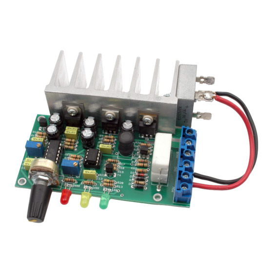
disadvantages. This module can be a standalone unit,
such as the model shown on the photographs, but
Characteristics
• charging of 12 V lead-acid batteries with a capacity of
10...100 Ah
• charging current regulation in the range of approx.
1...10 A
• battery overcharging protection
• multi-stage charging process
• power supply: 17 V transformer or factory rectifier
• PCB size: 103×54 mm
can also be an attachment to a simple, classic
rectifier. In both cases you receive an automatic
charger. Its diagram is shown in Figure 1 and it can
be divided into several blocks.
1. Current measurement block - built using lM358
chip (IC3A, IC3B). Positive output from the rectifier is
fed to the POW terminal and goes to a measuring
shunt R16 composed of two low-resistance power
resistors. Operational amplifier IC3B including
transistor T4 and adjacent components form a
current-to-voltage converter. At its output there is a
filter built of elements R20, C13 and amplifier IC3A.
Output signal is calibrated using precision
potentiometer R24 and goes to the microcontroller -
the signal marked CV.
2. Power stage - built with transistors T3 and T5. T3 is
used to control the voltage/current waveform
PDF
DOWNLOAD
ASSEMBLY DIFFICULTY
1
Advertisement
Table of Contents

Summary of Contents for AVT 3120
- Page 1 Automatic Charger For Lead Batteries kits DOWNLOAD ASSEMBLY DIFFICULTY The device monitors the charging process and Characteristics determines its optimal performance. The whole cycle is • charging of 12 V lead-acid batteries with a capacity of divided into 4 stages automatically switched 10...100 Ah depending on the battery charge level.
- Page 2 supplied to the battery. Transistor T5 with adjacent and adjacent components. Its task is to detect the components allow the MOSFET to be controlled halves of the sine wave applied on the battery DC directly from the microcontroller lead. voltage - this process will be discussed in more detail 3.
- Page 3 element. Waveforms in the circuit are shown in Figure can be obtained, the descending ramp marks the 2. Waveform A is the rectifier output, B is the beginning of the phase control period. The D superimposed output of the rectifier and the battery's waveform is the power stage control signal (MDR in DC voltage (VIN in the diagram).
- Page 4 can force a very high current due to the significant Stage IV - charging completed. When the green LED voltage difference. In this case, the circuit presented is on it indicates the end of the charging process, the reduces the charging current to 1/3 of the set range battery is fully charged and ready for use.
- Page 5 Photo 1 Once you cleaned the board visually inspected your voltage of approx. 29...30 V on pins 4 and 8 of the assembly, you can start your device up. You will need IC3 chip socket. If the voltages are correct then you a regulated power supply, a multimeter and a can move on to the next step.
- Page 6 Photo 2 Important note - the voltage should be increased current has a heavily distorted waveform and the slowly because the voltage measurement is cycled, ammeter may not indicate correctly, the current not continuous, and the voltage thresholds for measurement block also introduces slight distortions. switching stages have large hysteresis in the direction It is best to set the correct current in the middle of the falling voltage - switching from stage I to stage...
- Page 7 Photo 3 Photo 4...
- Page 8 AVT SPV reserves the right to make changes without prior notice.Installation and connection of the appliance not in accordance with the instructions, unauthorised modification of components and any structural alterations may cause damage to the appliance and endanger persons using it. In such a case, the manufacturer and its authorised representatives shall not be liable for any damage arising directly or indirectly from the use or malfunction of the product.
Need help?
Do you have a question about the 3120 and is the answer not in the manual?
Questions and answers