Table of Contents
Advertisement
Quick Links
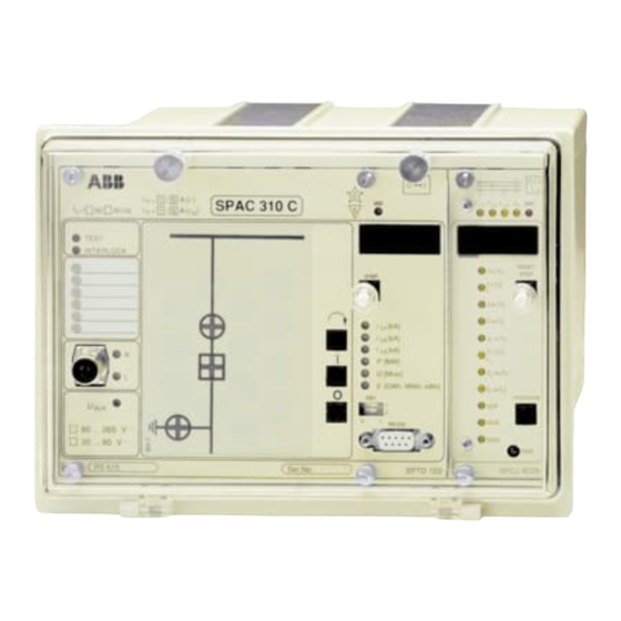
SPAC 310 C and SPAC 312 C
Feeder Terminal
User´s manual and Technical description
I
n =
f
n =
50
60 Hz
I
n =
TEST
INTERLOCK
GAS PRESSURE
MOTOR VOLTAGE
R
L
U
aux
_
80 ... 265 V
_
30 ... 80 V
RS 615
(
)
/
A
1
5
I
SPAC 310 C
( )
1
/
5
A
I
o
Ser.No.
O
I
2
IRF
5
STEP
I
[kA]
L1
I
[kA]
L2
I
[kA]
L3
I
P
[MW]
Q
[Mvar]
E
[GWh, MWh, kWh]
O
SG1
1
2
0
1
RS 232
SPTO 1D2
3
I
>
I
I
I
I
I
IRF
o
L1
L2
L3
RESET
I
/
I
>
n
STEP
t
[
]
>
s
k
I
/
I
>>
n
[ ]
t
>>
s
I
/
I
o >
n
[ ]
t
o >
s
k o
I
/
I
>>
o
n
t
[ ]
>>
s
o
PROGRAM
SGF
SGB
SGR
TRIP
SPCJ 4D29
Advertisement
Chapters
Table of Contents

Related Manuals for ABB SPAC 310 C


Summary of Contents for ABB SPAC 310 C
- Page 1 SPAC 310 C and SPAC 312 C Feeder Terminal User´s manual and Technical description > SPAC 310 C 60 Hz TEST INTERLOCK RESET GAS PRESSURE > STEP STEP MOTOR VOLTAGE > >> >> [kA] [kA] o > [kA] o >...
-
Page 2: Table Of Contents
Technical data ......................17 Exchange and spare parts ....................21 Maintenance and repairs ....................21 Order information ......................21 The user´s manual for the feeder terminal SPAC 310 C/SPAC 312 C is composed of the following partial manuals: General description 1MRS 750747-MUM EN... -
Page 3: Area Of Application
OPTIC SPA-BUS FEEDER PROTECTION AND CONTROL UNIT FEEDER PROTECTION FEEDER PROTECTION FEEDER PROTECTION AND CONTROL UNIT AND CONTROL UNIT AND CONTROL UNIT Fig. 1. Distributed protection and control system based on feeder terminals SPAC 310 C or SPAC 312 C. - Page 4 - ENERGY CONTROL - CB AND DISCONNECTOR STATUS - CB LOCAL AND REMOTE CONTROL O <-> I - MIMIC DISPLAY - INTERLOCKING READY SPAC 31_ C Fig. 2. Basic functions of the feeder terminal SPAC 310 C or SPAC 312 C...
-
Page 5: Design
SPGU 240A1 or SPGU 48B2 Energizing input module Includes matching transformers and their tuning electronics SPTE 4F1 (SPAC 310 C) or for three phase currents and neutral current. SPTE 4F2 (SPAC 312 C) Includes the motherboard with three signalling output con- tacts and electronics for the mA inputs. - Page 6 3I>> Io> Io>> Fig. 3. Block diagram for the feeder terminals SPAC 310 C and SPAC 312 C Overcurrent and earth-fault protection module SPCJ 4D29 Control module SPTO 1D2 I/O module SPTR 3B12 or SPTR 3B13 for digital inputs and contact outputs...
-
Page 7: Protection Functions
Protection functions The overcurrent protection of the combined neously starting the corresponding timing cir- overcurrent and earth-fault protection module cuit. When the set operating time has elapsed, a Phase overcurrent SPCJ 4D29 has two operating stages, a low-set tripping command is delivered. Correspond- protection stage and a high-set stage. -
Page 8: Control Functions
Control functions The control module SPTO 1D2 is used for The control module is also used for controlling reading the status information of circuit-break- one object e.g. a circuit-breaker, locally or with General ers and disconnectors.The module indicates the the opening or closing commands received over status locally by means of LED indicators and the SPA bus. - Page 9 Measurement Both the control module SPTO 1D2 and the The control module measures the active and functions combined overcurrent and earth-fault module reactive power via two mA inputs. External SPCJ 4D29 measures analog signals. measuring transducers have to be used. The mA signals are scaled to actual MWs and Mvars and The combined overcurrent and earth-fault mod- the data is indicated locally and can be transmit-...
-
Page 10: Application
Mounting and brackets. dimension drawings Flush mounting case 214 ±1 Panel cut-out Surface mounting case Fig. 4. Mounting and dimension drawings of feeder terminals SPAC 310 C and SPAC 312 C... - Page 11 CHANNEL 3/I SPA-ZC7_ SERIAL BUS, RS 485 SPAC 310 C Fig. 5. Connection diagram for SPAC 310 C. In SPAC 312 C the rated neutral current for terminal numbers 25-26 is 1 A and for terminal numbers 25-27 0.2 A...
- Page 12 , 5A Current I , 1A 25-26 Neutral current I , 5A in SPAC 310 C or 1A in SPAC 312 C 25-27 Neutral current I , 1A in SPAC 310 C or 0.2A in SPAC 312 C 61-62 Auxiliary power supply. Positive voltage should be connected to...
-
Page 13: Intermodular Control Signal Exchange
The scheme below illustrates how the SPTE 4F_ SPTE 4F_ SPTR 3B_ Fig. 6. Intermodular control signals of SPAC 310 C and SPAC 312 C... - Page 14 Default value SGF1/4 Selection of breaker failure protection SGF2/7 No function in SPAC 310 C or SPAC 312 C SGF2/8 No function in SPAC 310 C or SPAC 312 C SGB/1 Forms from a voltage connected to input 8 a blocking signal for the tripping of the I>...
-
Page 15: Terminals And Wiring
Terminals and wiring INTER- LOCK Fig. 7. Rear view of feeder terminal SPAC 310 C and SPAC 312 C All external conductors are connected to the The signalling contact outputs are connected to terminal blocks on the rear panel. Terminal the multi-pole connector X1. - Page 16 The start-up should be done according to the The programming can be done via the front Start-up following instructions. Checks1 and 2 have to panel RS 232 connection or the rear panel RS be performed before the auxiliary power supply 485 connection by using a SPA protocol.
- Page 17 Technical data Energizing inputs Rated current I - overcurrent unit of SPAC 310 C and SPAC 312 C - earth-fault unit of SPAC 310 C - earth-fault unit of SPAC 312 C 0.2 A Thermal withstand capability - continuous 0.8 A...
- Page 18 Contact outputs Control output numbers X0/65-66 and 85-86 - rated voltage 250 V ac or dc - continuous carry - make and carry for 0.5 s 30 A - make and carry for 3 s 15 A - breaking capacity for dc, when the control circuit time constant L/R≤...
- Page 19 Low-set earth-fault stage I > - current setting range 0.1…0.8 x I - operation modes to be selected - definite time operation - operating time t > 0.05…300 s - inverse definite minimum time (IDMT) mode as per IEC 255-4 and BS 142 Extremely inverse Very inverse Normal inverse...
- Page 20 Test voltages *) Dielectric test voltage (IEC 255-5) 2 kV, 50 Hz, 1 min 5 kV, 1.2/50 µs, 0.5 J Impulse test voltage (IEC 255-5) Insulation resistance (IEC 255-5) >100 MΩ, 500 V dc Disturbance tests *) High-frequency (1 MHz) disturbance test (IEC 255-22-1) - common mode 2.5 kV...
-
Page 21: Order Information
Power supply module, 80…265 V ac or dc SPGU 240 A1 Power supply module, 18…80 V dc SPGU 48B2 Housing without plug in modules, SPAC 310 C SPTK 4F1 Housing without plug in modules, SPAC 312 C SPTK 4F2 When the protection relay is operating under... - Page 22 Open status = red colour Closed status = red colour Closed status = green colour Fig. 8. Standard configuration plates for SPAC 310 C and SPAC 312 C Note! Regardless of the configuration plate the control module always has the default configuration...
- Page 23 SPAC 31__ C CONFIGURATION CLIENT SUBSTATION FEEDER SINGLE LINE DIAGRAM NOTES DRAWN BY DATE Fig. 9. Form for sketching customized configuration plates for SPAC 310 C and SPAC 312 C. The circles of the configuration plate illustrate the LED indicators.
- Page 25 SPTO 1D2 Control module User´s manual and Technical description SPAC 3__ C 60 Hz TEST INTERLOCK GAS PRESSURE STEP MOTOR VOLTAGE [kA] [kA] [kA] [MW] [Mvar] [GWh, MWh, kWh] RS 232 80 ... 265 V 30 ... 80 V RS 615 Ser.No.
- Page 26 SPTO 1D2 1MRS 750748-MUM EN Issued 97-08-26 Control module Version A (replaces 34 SPTO 4 EN1) Checked Approved Data subject to change without notice Description of functions ....................3 Contents Control functions ...................... 3 Measurement functions ..................... 3 Block diagram ......................4 Front panel ........................
- Page 27 The control module type SPTO 1D2 reads The control module is able to give OPEN and Description binary input signals and indicates the status of CLOSE commands for one object. The com- of functions these signals locally and remotely. The control mands may be given by means of the local push- module also performs OPEN and CLOSE com- buttons, via the SPA bus or the input channels...
-
Page 28: Block Diagram
Block diagram Simplified block diagram of the control module SPTO 1D2 is shown in Fig. 1. SPA-bus Open/close output control Indication Channels 1…3 Read status Open / & Close Inter- locking Enable SPA-bus Conditional Channels direct 4…13 Read output status control Indication Chann. -
Page 29: Front Panel
Front panel Simplified device Type designation and symbol rated values of the relay SPAC 3__ C Self-supervision package 60 Hz alarm indicator Operation indicators; Display for measured TEST output test and interlocked values INTERLOCK operation GAS PRESSURE STEP MOTOR VOLTAGE Indicators for input Display step button channels 4…9... -
Page 30: Indicators For Input Channels 4
Indicators for input The status of the input channels 4...9 is indi- indicator is memory controlled the LED indi- channels 4…9 cated locally on the front panel. Channel 4 refers cator remains lit until the channel is locally to the upmost red indicator and channel 9 to the reset by pressing the push-buttons STEP and lowest one. -
Page 31: I And O Push-Buttons
∩ , I and O push- The local control sequence is started by pressing The closing or opening command is given by the push-button ∩ (SELECT). After that the buttons using the I (close) or O (open) push-button. LED indicator of the object which has been Depending on the status of inputs 1…3 and defined controllable starts flashing. - Page 32 Also the serial communication parameters are of the data to be displayed is indicated by the red indicated by the four-digit display. The address digit at the extreme left of the display. Red digit Data to be displayed Serial communication address. May have a value within the range 0…254. The default value is 99.
- Page 33 RS 232 interface The 9-pin RS 232 interface on the front panel is The following serial communication param- to be used for programming the control module eters should be used: from a terminal or a PC. The control module SPTO 1D2 supervises the serial communica- - Number of data bits, 7 tion of the feeder terminal.
-
Page 34: Configuration
The control module SPTO 1D2 is able to The front panel indicators are numbered from Programming indicate the status of maximum 3 objects (cir- 101 to 116. These numbers are used when cuit breakers or disconnectors) and to control programming the feeder terminal configura- Configuration (open or close) one object. - Page 35 Example 2: Indicator 109 (S109) indicates the output 21 must be used for closing the same status read via input channel 2. Output 20 is object. The object is a circuit breaker and the used for opening the object which means that closed status is indicated by vertical red LEDs.
- Page 36 Example 3: To program a configuration similar The programmed configuration can be read to the default configuration 1 (indicator 109 CB indicator by indicator or with a single com- truck, indicator 110 CB and indicator 116 earth- mand. switch), the following commands are required: Example 4: To read the configuration of indica- >99WS198:0:XX tors 101…116 with one command only.
-
Page 37: Interlocking
Interlocking An interlocking program is used to inhibit the Example 5: In example 3 a configuration was closing or opening command for a controllable programmed. If the interlockings are not used object in certain situations. In practice, in the the programming continues with the following control module SPTO 1D2, the interlocking commands: enables the control operations, i.e. - Page 38 In SPTO 1D2 the following operand values can Example 6: How to store the result of a logic be used with operations LOAD, LOADN, AND, operation into a temporary register. ANDN, OR, ORN : >99WM200:LOAD 201:XX 1…3 = input channel number ;...
- Page 39 Example 8: Programming of an interlocking A configuration was programmed in example 3. logic. This example is related to example 3, the If the interlockings described above are taken circuit breaker is to be controlled. into use the programming continues with the following commands.
- Page 40 Conditional Direct The Conditional Direct Output Control logic Example 9: An interlocking logic was pro- Output Control controls the outputs OPEN, CLOSE and SIG- grammed in example 8. In this example a Con- NAL1…3. Outputs not used for controlling an ditional Direct Output Control logic is added object or for signalling the activation of inputs for SIGNAL 3 output.
- Page 41 Input channels The input channels 4…13 are used to read The position of the R/L keyswitch is without 4…13 binary signals other than circuit breaker and significance when the control outputs (OPEN disconnector status information. The binary or CLOSE) are controlled via inputs 4…13, but signals can be external contact signals or internal a check with the blocking logics is always made binary signals, e.g.
- Page 42 Outputs The control module SPTO 1D2 has five out- >99W2V5:0.5:XX puts: three signal outputs (SIGNAL1…3) and ; Set the open pulse length to 0.5 seconds two control outputs (OPEN and CLOSE). For >99W2V6:0.2:XX programming the outputs are coded in the fol- ;...
- Page 43 Scaling of The control module is able to measure three Active and reactive power measurements phase currents, active and reactive power and energy. The phase currents are measured via the The value of the active power is displayed locally 1 A or 5 A current inputs of the feeder terminal. and transferred in actual megawatts via the serial For measuring active and reactive power the bus.
- Page 44 Example 13: The scale of the measured active The following parameters must be defined for power ranges from -50 to 135 MW and the channel 7: corresponding mA range is -20…20 mA. S1 = definition of channel 7 >99WS91:1:XX 0 = general ON/OFF input (default) ;...
-
Page 45: Event Codes
Event codes Over the SPA bus substation level data commu- Most of the event codes and the events repre- nicator can read the event data, change in status, sented by these may be included in or excluded produced by the control module SPTO 1D2. from the event reporting by writing an event The events are represented by the event codes mask (V155) to the module. - Page 46 The control module has the following event codes: Channel Code Event Number re- Default value presenting of event factor event Key switch to LOCAL position Key switch to REMOTE position Output test switch SG1/1 ON Output test switch SG1/1 OFF V155 = 3 1…3 Change in status;...
- Page 47 Programming If all the parameters are programmed at the same Example 19: Select a user defined configuration quick reference time the following instructions should be used and interlocking. when changing between program and run mode and when storing the parameters. >99WS198:0:XX ;...
- Page 48 Serial communica- Apart from the event codes the substation level the memory (V-data), and some other data. tion parameters data communicator is able to read, over the Further, part of the data can be altered by SPA-bus, all input data (I-data) of the module, commands given over the SPA-bus.
- Page 49 Data Channel Code Data Values direction Scaling of current measurement RW(e) 0.00…10000.00 Low limit for mA signal of active power RW(e) -20…+20 mA High limit for mA signal of active power RW(e) -20…+20 mA Low limit for mA signal of react. power RW(e) -20…+20 mA High limit for mA signal of react.
- Page 50 Data Channel Code Data Values direction Interlocking and Conditional Direct M200 RW(e) operation = Output Control program LOAD, LOADN (format; operation, operand) M300 AND, ANDN OR, ORN operands for interlocking = status closed (1…3) or active (4…13) status undefined (101…103) status open (201…203) No.
- Page 51 Data Channel Code Data Values direction Memory controlled function of the 4…9 RW(e) 0 = not memory indicators of the binary inputs controlled 1 = memory controlled Event delay; —>activated 4…13 RW(e) 0.0, or 0.1…60.0 s Event delay; —>reset 4…13 RW(e) 0.0, or 0.1…60.0 s Event reporting...
- Page 52 Data Channel Code Data Values direction Type designation of the module SPTO 1D2 Reading of event register Time, channel number and event code Re-reading of event register Time, channel number and event code Reading of module status 0 = normal state information 1 = module been subject to automatic reset...
-
Page 53: Default Values Of The Parameters
Default values of The parameters stored in the EEPROM have power supply was connected. The push-but- the parameters been given default values after factory testing. tons have to be pressed until the display is lit. All the default values have been stored in the EEPROM by pressing the push-buttons STEP The following table gives the default values of and SELECT at the same time as the auxiliary... -
Page 54: Technical Data
Parameter Channel Code Default value Event delay; —>activated 4…13 0.0 s Event delay; —>reset 4…13 0.0 s Event reporting 1…13 0 = event reporting enabled Load default values after EEPROM failure V152 1 = inhibited Event mask V155 Event mask 1…3 V155 1875... -
Page 55: Appendix 1, Default Configuration And Interlocking 1
Default configuration and interlocking 1 is se- Interlocking Appendix 1 lected by giving variable S100 the value 1. The other parameters have the values given in the The following rules apply for interlocking: Default configuration chapter "Default values of the parameters" and interlocking 1 - The CB can always be opened. -
Page 56: Appendix 2, Default Configuration And Interlocking 2
Default configuration and interlocking 2 is se- Interlocking Appendix 2 lected by giving variable S100 the value 2. The other parameters have the values given in the The following rules apply for interlocking: Default configuration chapter "Default values of the parameters" and interlocking 2 - The CB can always be opened. - Page 57 Default configuration and interlocking 10 is Interlocking Appendix 3 selected by giving variable S100 the value 10. The other parameters have the values given in The interlocking is defined with the following Default configuration the chapter "Default values of the parameters". rules: and interlocking 10 - The CB can always be opened.
- Page 59 General characteristics of D-type relay modules User´s manual and Technical description 3 > Relay symbol Fastening screw Self-supervision alarm indicator Indicators for measured (Internal Relay Fault) quantities Display, 1 + 3 digits RESET > STEP t [ ] > Reset / Step push-button >>...
- Page 60 1MRS 750066-MUM EN General characteristics Issued 95-04-12 of D type relay modules Version A (replaces 34 SPC 3 EN1) Checked JH Approved TK Data subject to change without notice Front panel lay-out ......................1 Contents Control push buttons ..................... 3 Display ...........................
-
Page 61: Display
The front panel of the relay module contains certain position in the main menu to the corre- Control two push buttons. The RESET / STEP push sponding submenu, for entering the setting push-buttons button is used for resetting operation indicators mode of a certain parameter and together with and for stepping forward or backward in the the STEP push button for storing the set values. -
Page 62: Settings
Part of the settings and the selections of the Selector switch- operation characteristic of the relay modules in Switch No Pos. Weigth Value groups SGF, SGB various applications are made with the selector and SGR switchgroups SG_ . The switchgroups are soft- ware based and thus not physically to be found in the hardware of the relay module. -
Page 63: Setting Mode
NOTE! During any local man-machine com- any doubt about the settings of the module to be munication over the push buttons and the dis- inserted, the setting values should be read using play on the front panel a five minute time-out a spare relay unit or with the relay trip circuits function is active. - Page 64 MAIN MENU SUBMENUS STEP 0.5 s PROGRAM 1 s Normal status, display off Current on phase L1 Current on phase L2 Current on phase L3 REV. STEP 0.5 s FWD. STEP 1 s Neutral current Io SUBMENUS Second setting Main setting Actual start value I>...
- Page 65 Example 1 Operation in the setting mode. Manual setting for the main setting is 0.80 x I and for the of the main setting of the start current value I> second setting 1.00 x I . The desired main start of an overcurrent relay module.
- Page 66 RESET STEP Set the digit with the STEP push button. 1 1. 0 5 PROGRAM Press the PROGRAM push button to make the decimal point flash. 1 1. 0 5 RESET STEP If needed, move the decimal point with the STEP push button.
- Page 67 Example 2 Operation in the setting mode. Manual setting SGF1/1and SGF1/3 are to be set in position 1. of the main setting of the checksum for the This means that a checksum of 005 should be switchgroup SGF1 of a relay module. The initial the final result.
- Page 68 RESET STEP The switch position is altered to the desired position 1 by pressing the STEP push button once. PROGRAM Using the same procedure the switches SGF 1/ 5 x 1 s 4...8 are called up and, according to the exam- ple, left in position 0.
- Page 69 The parameter values measured at the moment Submenu 2 of register A contains a bus commu- Recorded when a fault occurs or at the trip instant are nication monitor for the SPAbus. If the protec- information recorded in the registers. The recorded data, tion relay, which contains the relay module, is except for some parameters, are set to zero by linked to a system including a contol data...
-
Page 70: Trip Test Function
Register 0 also provides access to a trip test The selected starting or tripping is activated by Trip test function function, which allows the output signals of the simultaneous pressing of the push buttons relay module to be activated one by one. If the STEP and PROGRAM. - Page 71 Example 3 Trip test function. Forced activation of the outputs. Step forward on the display to register 0. RESET STEP n x 1 s 0 0 0 0 Press the PROGRAM push button for about 3 > five seconds until the three green digits to the right.
- Page 72 To proceed to the next position press the PRO- 3 > GRAM push button for about 1 second until the indicator of the second setting starts flash- 0 0 0 0 ing. RESET > STEP PROGRAM t [ ] > >>...
-
Page 73: Operation Indicators
A relay module is provided with a multiple of indicator is reset by means of the RESET push Operation separate operation stages, each with its own button of the relay module. An unreset opera- indication operation indicator shown on the display and a tion indicator does not affect the function of the common trip indicator on the lower part of the protection relay module. - Page 75 SPCJ 4D29 Overcurrent and earth-fault relay module User´s manual and Technical description > RESET > STEP > >> >> o > o > >> >> PROGRAM TRIP SPCJ 4D29...
-
Page 76: Fault Codes
SPCJ 4D29 1MRS 750119-MUM EN Issued 96-06-17 Combined overcurrent Version B (replaces 34 SPCJ 8 EN1) Checked TK and earth-fault relay Approved TK module Data subject to change without notice Features .......................... 2 Contents Description of function ....................3 Block diagram ......................... 5 Front panel ........................ -
Page 77: Description Of Function
The phase overcurrent unit of the relay module Note! Description of SPCJ 4D29 is designed for single-phase, two- The operation of the low-set stage based on function phase or three-phase overcurrent protection. It inverse time characteristic will be blocked by includes two overcurrent stages, i.e. - Page 78 Earth-fault unit The non-directional earth-fault unit of the relay range, 0.05...300 s. When the inverse time module SPCJ 4D29 is a single-pole earth-fault operation characteristic (IDMT) is selected, four unit. It contains two earth-fault stages, i.e. a internationally standardized and two comple- low-set earth-fault stage I >...
-
Page 79: Block Diagram
Block diagram SGR3 / 1 SGR1 / 1 50 ms SGR3 / 2 SGR2 / 1 I> t>, k SGR2 / 2 SGR1 / 2 SGR3 / 3 SGF1 / 1 RESET+ SGR1 / 3 SGB / 6 SGF1 / 2 SGB / 1 SGF2 / 7 SGF1 / 3... -
Page 80: Front Panel
Front panel > Indicators for the measured phase currents I and the residual current I RESET Indicator for the start current of the I> stage > STEP Indicator for the operate time t> or time multiplier k > of the I> stage Indicator for the start current of the I>>... -
Page 81: Start And Operation Indicators
Both overcurrent stages have their own start has operated. The start or operation indicators Start and indicators and operation indicators shown as are reset by pushing the RESET push-button. operation figures on the digital display. Further, all the The function of the relay module is not affected indicators protection stages share a common red LED by an unreset indicator. -
Page 82: Settings
The setting values are shown by the right-most symbol of the setting quantity shows the quan- Settings three digits of the display. When lit, the LED tity currently being displayed. indicators on the front panel adjacent to the I>/I Start current of the I> stage as a multiple of the rated current of the used energizing input. -
Page 83: Selector Switches
Additional functions required in various appli- groups are set. Under normal service conditions Selector switches cations are selected with switchgroups SGF, only the checksums are shown. Switchgroups SGB and SGR indicated on the front panel. The SGF2, SGR2 and SGR3 are found in the sub- numbering of the switches, 1...8, and the switch menus of the main menus of switchgroups SGF positions 0 and 1 are shown when the switch-... - Page 84 Function switch- Switch Function group SGF2 SGF2/1 Switches SGF2/1...4 are used for selecting the operation characteristic of the start SGF2/2 indicators of the different stages. When the switches are in position 0 the start signals SGF2/3 are all automatically reset when the fault is cleared. To give the indicator of a stage the SGF2/4 hand reset mode of operation, the corresponding switch is set in position 1: SGF2/1 = 1 equals manual reset mode for the start indication of stage I>...
- Page 85 Blocking or control Switch Function signal configuration switchgroup SGB SGB/1 Switches SGB/1...4 are used for routing an external blocking signal BS to one or more SGB/2 of the protection stages of the relay module. When the switches all are in position 0 SGB/3 no stage is blocked.
- Page 86 Output relay matrix SGR1 The switches of switchgroup SGR1 are used to select the start and operate signals switchgroups SGR1, to be routed to outputs SS1 and TS2. SGR2 and SGR3 SGR2 The switches of switchgroup SGR2 are used for routing the operate signals of the protection stages to the outputs SS2 and SS3.
-
Page 87: Measured Data
Switch Function Factory Checksum number setting value SGR3/1 When SGR3/1 = 1, the start signal of the I> stage is routed to TS1 SGR3/2 When SGR3/2 = 1, the trip signal of the I> stage is routed to TS1 SGR3/3 When SGR3/3 = 1, the start signal of the I>> stage is routed to TS1 SGR3/4 When SGR3/4 = 1, the trip signal of the I>>... -
Page 88: Recorded Information
The left-most red digit shows the address of the The // symbol in the text indicates that the item Recorded register and the right-most three digits the re- following the symbol is found in a submenu. information corded value. Register/ Recorded information STEP Phase current I displayed as a multiple of the rated current of the used input of the... - Page 89 Register/ Recorded information STEP Display of blocking signals and other external control signals. The right-most digit indicates the state of the blocking input of the module. The following states may be indicated: 0 = no blocking signal 1 = blocking or control signal BS active. The function of the external control signal on the relay unit is determined by the settings of switchgroup SGB From register "0"...
-
Page 90: Menu And Register Chart
Menu and register chart MAIN MENU SUBMENUS STEP 0.5 s PROGRAM 1 s Normal status, display off Current on phase L1 Current on phase L2 Current on phase L3 REV. STEP 0.5 s FWD. STEP 1 s Neutral current Io SUBMENUS Second setting Main setting... - Page 91 The procedures for entering a submenu or a described in detail in the manual "General char- setting mode and the method of performing the acteristics of D type relay modules". A short settings and the use of the TEST mode are form guide to the operations is shown below.
- Page 92 SGF1/6...8 for the earth-fault stage I > sets, named RI type and RXIDG type, accord- (see chapter "Selector switches", page 7). ing to ABB standards. IDMT Four standard curves named extremely inverse, The slope of the time/current curve sets is deter- mined by the constants α...
- Page 93 RI-type The RI-type characteristic is a special character- where characteristic istic used mainly in combination with existing t = operate time in seconds mechanical relays. The characteristic is based on k = time multiplier the following mathematical expression: I = measured phase current I>...
- Page 94 0.09 0.08 0.07 0.06 0.05 0.04 0.05 0.03 0.02 6 7 8 9 10 20 I/I> Fig. 3. Extremely inverse-time characteristics of the overcurrent and earth-fault unit SPCJ 4D29.
- Page 95 0.09 0.08 0.07 0.06 0.05 0.05 0.04 0.03 0.02 6 7 8 9 10 20 I/I> Fig. 4. Very inverse-time characteristics of the overcurrent and earth-fault unit SPCJ 4D29.
- Page 96 0.05 0.09 0.08 0.07 0.06 0.05 0.04 0.03 0.02 7 8 9 10 20 I/I> Fig. 5. Normal inverse-time characteristics of the overcurrent and earth-fault unit SPCJ 4D29.
- Page 97 0.05 I/I> 7 8 9 Fig. 6. Long-time inverse-time characteristics of the overcurrent and earth-fault unit SPCJ 4D29.
- Page 98 0.05 0.09 0.08 0.07 0.06 0.05 0.04 0.03 0.02 6 7 8 9 10 20 I/I> Fig. 7. RI-type inverse-time characteristics of the overcurrent and earth-fault unit SPCJ 4D29.
- Page 99 0.09 0.08 0.07 0.06 0.05 0.04 0.4 0.5 0.05 0.03 0.02 7 8 9 10 I/I> Fig. 8. RXIDG-type inverse-time characteristics of the overcurrent and earth-fault unit SPCJ 4D29.
- Page 100 - Inverse time characteristic acc. to BS 142 and IEC 255-4 Extremely inverse Very inverse Normal inverse Long-time inverse - special characteristic acc. to ABB standards RI-type inverse RXIDG-type inverse - time multiplier k 0.05...1.00 Reset time, typ. 40 ms Retardation time <30 ms...
- Page 101 High-set earth-fault stage I >> or ∞, infinite Start current I >> 0.1...10.0 x I Start time, typ. 40 ms Operate time 0.05...300 s Reset time, typ. 40 ms Drop-off/pick-up ratio, typ. 0.98 ±2% of set value or ±25 ms Operate time accuracy ±3% of set value Operation accuracy...
- Page 102 Code Event Weight factor Default value of the factor Starting of stage I > Resetting of starting of stage I > Operation of stage I > Resetting of operation of stage I > Starting of I >> stage Resetting of starting of stage I >>...
- Page 103 Data to be trans- In addition to the spontaneous data transfer the All the data are available in channel 0. ferred via the fibre- SPA bus allows reading of all input values (I- optic serial bus values), setting values (S-values), information R = data to be read from the unit recorded in the memory (V-values), and some W = data to be written to the unit...
- Page 104 Data Code Data Values direction Memorized I> start signal 0 = signal not active 1 = signal active Memorized I> operate signal 0 = signal not active 1 = signal active Memorized I>> start signal 0 = signal not active 1 = signal active Memorized I>>...
- Page 105 Data Code Data Values direction MAIN SETTING VALUES Start current of stage I>, R, W (P) 0.5...5.0 x I main setting Operate time or time multiplier R, W (P) 0.05...300 s of stage I>, main setting 0.05…1.0 Start current of stage I>>, R, W (P) 0.5...40.0 x I main setting...
- Page 106 Data Code Data Values direction Checksum of switchgroup SGF1, R, W (P) 0...255 second setting Checksum of switchgroup SGF2, R, W (P) 0...255 second setting Checksum of switchgroup SGB, R, W (P) 0...255 second setting Checksum of switchgroup SGR1, R, W (P) 0...255 second setting Checksum of switchgroup SGR2,...
- Page 107 Data Code Data Values direction Remote control of settings V150 R, W 0 = main settings activated 1 = second settings activated, see chapter "Description of function" Event mask word for V155 R, W 0...255, see chapter overcurrent events "Event codes" Event mask word for V156 R, W...
- Page 108 Shortly after the internal self-supervision system indicates the fault type. When a fault code Fault codes has detected a permanent relay fault, the red IRF appears on the display, the code number should indicator is lit and the output relay of the self- be recorded and given to the authorized repair supervision system operates.
- Page 110 ABB Oy Substation Automation P.O.Box 699 FIN-65101 VAASA Finland Tel. +358 (0)10 22 11 Fax.+358 (0)10 22 41094 www.abb.com/substationautomation...
Need help?
Do you have a question about the SPAC 310 C and is the answer not in the manual?
Questions and answers