
Summary of Contents for Oxford Instruments ANDOR PCUB-110
- Page 1 PCUB-110 Version 2.2 revised 19 Mar 2015 User Guide Precision Control Unit PCUB-110 for the ALC-601 in Revolution XD and WD systems andor.com © Andor Technology 2015...
-
Page 2: Table Of Contents
PCUB-110 TABLE OF CONTENTS SECTION 1: INTRODUCTION ....................... 8 ABOUT THE PCUB-110 ......................8 INTENDED USE ........................8 TECHNICAL SUPPORT ......................9 DISCLAIMER ......................... 10 COPYRIGHT AND PROTECTIVE NOTICES ................10 TRADEMARKS AND PATENT INFORMATION ............... 10 SECTION 2: PRODUCT OVERVIEW ....................11 ANDOR IQ SOFTWARE ...................... - Page 3 PCUB-110 SECTION 4: INSTALLATION ....................... 21 INSTALLATION OF THE PCU UNIT ..................21 4.1.1 Location and Mounting ..................... 21 4.1.2 Ventilation ........................21 4.1.3 Assembly ........................21 4.1.4 Power Connection and Protective Earthing ............21 INSTALLING THE DAC CARD ....................22 4.2.1 DIP Switch Settings ....................
- Page 4 PCUB-110 APPENDIX A: GLOSSARY ........................32 APPENDIX B: OTHER INFORMATION ....................33 Version 2.2 rev 19 Mar 2015...
- Page 5 PCUB-110 Revision History Version Released Description 04 Jul 2008 Initial Release 30 Sep 2008 Updated to Andor presentation 30 Nov 2010 Updated format and document structure. Warning information updated from general to product specific warning. 05 Dec 2010 Updated China office contact details. Removed terms and conditions of sales link.
- Page 6 PCUB-110 Safety and Warning Information PLEASE READ THIS INFORMATION FIRST If the equipment is used in a manner not specified by Andor, the protection provided by the equipment may be impaired. The RF and Therm connectors on the front panel must be connected before power-on. See Section 5.1, “Emergency Disconnection”.
- Page 7 PCUB-110 eneral afety ymbolS The following are explanations of the safety symbols found on this product: Caution, risk of electric shock. Caution, risk of danger. Caution, consult technical manual before servicing. anual andlinG Due to the delicate nature of some of the components within, care must be exercised when handling this product. Proper manual handling techniques are important when installing the Revolution XD or WD system to ensure that the integrity of the product is safeguarded and individuals involved are not exposed to unnecessary manual handling risks, such as:...
-
Page 8: Section 1: Introduction
PCUB-110 INTRODUCTION SECTION 1: INTRODUCTION Thank you for purchasing an Andor Precision Control Unit (PCU). This manual is aimed at covering the installation, operation and maintenance of the PCUB-110, which is the control unit for Andor Revolution XD and WD systems. Before you start to use the product, read this manual thoroughly and follow the instructions given. -
Page 9: Technical Support
PCUB-110 INTRODUCTION 1.3 t eCHniCal uPPort If you have any questions regarding the use of this equipment, please contact the representative* from whom your system was purchased, or: Europe Andor Technology Andor Technology 7 Millennium Way 425 Sullivan Avenue Springvale Business Park Suite # 3 Belfast South Windsor... -
Page 10: Disclaimer
Andor and the Andor logo are trademarks of Andor Technology. Andor Technology is an Oxford Instruments company. All other marks are property of their owners. Borealis includes technology covered by the following patents: US Patent No. 8,275,226, EP Patent No. 2196839, US Patent No. 8,670,178 and CA Patent No. 2779146. -
Page 11: Section 2: Product Overview
PCUB-110 PRODUCT OVERVIEW SECTION 2: PRODUCT OVERVIEW The Revolution XD and WD Systems provide a framework for Andor’s laser spinning disk, live-cell confocal microscopy solutions, which combine our award winning iXon Electron Multiplying CCD (EMCCD) camera with the renowned Yokogawa CSU-X1 and CSU-W1. The Revolution XD System (shown below) encompasses a range of complementary components, both hardware and software, that fit seamlessly together creating a complete confocal microscopy solution. -
Page 12: The Pcub-110 Precision Control Unit
PCUB-110 PRODUCT OVERVIEW 2.2 t PCub-110 P reCiSion ontrol The PCUB-110 is the main control unit of the Revolution XD Microscopy System. Figure 3: PCUB-110 Precision Control Unit The PCUB-110 has the following functions: • Control of the AOTF (Acousto-Optical Tuneable Filter) in the ALC, including active blanking, which allows laser light though the AOTF only when the camera is in Live mode, or acquiring an image. -
Page 13: Pci Dac Card
PCUB-110 PRODUCT OVERVIEW 2.3 PCi daC C The PCU is controlled via PC software (usually Andor iQ) using a PCI “DAC card”, which is the Measurement Computing PCIM-DDA06-16. Figure 4: Measurement Computing PCIM-DDA06-16 PCI DAC Card Version 2.2 rev 19 Mar 2015... -
Page 14: Section 3: Specifications
PCUB-110 SPECIFICATIONS SECTION 3: SPECIFICATIONS 3.1 P ower uPPly PLEASE NOTE that this product does not currently use a universal power supply. It has been set in production to use either the nominal European, etc., mains supply voltage, or the North America, etc., mains supply voltage. This product must be powered via the rear 3-pin IEC C14 connector from an a.c. -
Page 15: Interface Specifications
PCUB-110 SPECIFICATIONS 3.3 i nterfaCe PeCifiCationS This section is focused on the electrical specifications of the interfaces, rather than their operation. Information on operation (including switches) may be found in Section 5, “Operation”. The following pictures show the front and rear panels of the product with the connectors referred to in this section. 3.3.1 f ront anel... - Page 16 PCUB-110 SPECIFICATIONS 3.3.1.1 d i/o P (ttl t iGital ortS riGGerS These ports can be used for digital inputs (8 dedicated ports) or outputs (separate 8 dedicated ports) under the control of software. These are opto-isolated for protection. Inputs Connector Type: BNC Female (50 ohm size) Signal Type: Digital Input...
-
Page 17: Aotf Control
PCUB-110 SPECIFICATIONS 3.3.1.2 aotf C ontrol This interface is used for control of the AOTF (Acousto-Optical Tuneable Filter) in the ALC. RF Out Connector Type: SMA Female Signal Type: RF output Electrical Specification: This is a dedicated connection to the “RF In” connector of the ALC and is not designed for other uses. -
Page 18: Analogue Piezo Control
PCUB-110 SPECIFICATIONS 3.3.1.3 a naloGue iezo ontrol This interface is used for control of an analogue controlled Piezo Z-stage. A5 – Piezo Connector Type: BNC Female (50 ohm size) Signal Type: Analogue Output Electrical Specification: Parameter Specification Resolution 16 bits Voltage ranges ±10 V, ±5, 0 to 10 V, 0 to 5 V. -
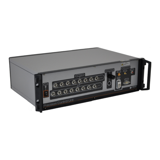
Page 19: Rear Panel Interface
PCUB-110 SPECIFICATIONS 3.3.2 r anel nterfaCe Active Blanking Control (Aux, Fire 1, Fire 2 and On/ Off switch Mains IEC C14 Fan exhaust DAC Card D-type connector with fuse vent connector Figure 6: Rear panel of the PCUB-110 3.3.2.1 a Ctive lankinG ontrol... -
Page 20: Dac Card Connector
PCUB-110 SPECIFICATIONS 3.3.2.2 daC C onneCtor This is a dedicated connection to the Measurement Computing PCIM-DDA06-16 PCI DAC card and is not designed for other uses. Parameter Specification PCI Standard PCI 2.1 PCI Supply Voltage PCI Supply Current 965 mA typical, 1206 mA maximum PCI Bus Width 32-bit PCI Bus Speed... -
Page 21: Section 4: Installation
PCUB-110 INSTALLATION SECTION 4: INSTALLATION This product will usually be supplied as part of a system, and will be installed by Andor Installation Technician or a trained Andor Systems distributor. The following is only provided to augment this. 4.1 i PCu u nStallation of tHe 4.1.1 l... -
Page 22: Installing The Dac Card
PCUB-110 INSTALLATION 4.2 i daC C nStallinG tHe The PCU is controlled via PC software (usually Andor iQ) using a PCI DAC card, which is the Measurement Computing PCIM-DDA06-16. Figure 7: PCI DAC Card Showing DIP Switches Along Upper Edge 4.2.1 diP S witCH ettinGS... -
Page 23: Installing The Pci Card
PCUB-110 INSTALLATION 4.2.2 i PCi C nStallinG tHe The PCI DAC Card is installed in the same manner as you would fit most other add-in cards such as graphics cards. PLEASE NOTE: Consult the manual supplied with your computer to ensure correct installation of the controller card for your particular model as models change frequently. - Page 24 PCUB-110 INSTALLATION At this point, put on the ESD wrist strap supplied with your camera and attach the crocodile clip to a suitable earth point on the PC: Figure 12: Attaching ESD strap between wrist and earth point on the PC IMPORTANT NOTE: THE ESD STRAP MUST BE WORN AT ALL TIMES WHEN HANDLING THE PCI CARD.
-
Page 25: Installation Of Cabling
PCUB-110 INSTALLATION 4.3 i nStallation of ablinG 4.3.1 P ower ablinG See Section 4.1.4 Power Connection and protective Earthing. 4.3.2 daC C ablinG The Measurement Computing C37FFS-10 cable supplied for connecting the DAC Card in the PC to the D-type connector on the PCU is shown below: Figure 14: DAC Card Cable Connect the cable into the DAC Card in the computer at one end and the other into the DAC connector on the rear panel... -
Page 26: Alc Aotf Cabling
PCUB-110 INSTALLATION 4.3.3 alC aotf C ablinG Connect the supplied SMA and SMC coaxial cables between the RF and Therm ports on the ALC and the PCU. Ensure that these are fitted without damage to the connectors and that they lock, but are only finger-tight. Overtightening may damage the connectors. -
Page 27: Mpu Cabling
PCUB-110 INSTALLATION Figure 18: BNC to SMB Cable Connection between PCU Fire 1 and Camera Fire For a Single Camera under iQ 1.10.x using Fast LZ (Lambda Z) A different configuration is required. Please contact Andor support for information. For a Second Camera using iQ2.x This is, for example, when using the DCIS Dual Camera Adapter. -
Page 28: Frappa Cabling
PCUB-110 INSTALLATION 4.3.6 fraPPa C ablinG Connect “D-OUT” on the SPU to “AUX” on the PCU rear panel. Figure 20: FRAPPA Connection for PCU 4.3.7 a naloGue iezo ablinG Connect a 3m BNC cable from “A5 Piezo” on the PCU front panel to the Piezo Analogue Input of the Piezo Controller. 4.4 i nStallinG tHe oftware... -
Page 29: Section 5: Operation
PCUB-110 OPERATION SECTION 5: OPERATION If the equipment is used in a manner not specified by Andor, the protection provided by the equipment may be impaired. 5.1 e merGenCy iSConneCtion In case of emergency, the disconnecting device is the mains lead. This will either be the mains lead connected to the product, or in the case of a cabinet-based system the mains lead to the cabinet. - Page 30 PCUB-110 OPERATION ON/OFF Switch Figure 22: Active Blanking Switch on Rear Panel On/ Off Switch “On” activates active-blanking and does not require any of the Fire 1, Fire 2 and Aux inputs to be high. “Off” just allows active blanking to be controlled by the inputs. Version 2.2 rev 19 Mar 2015...
-
Page 31: Section 6: Maintenance
PCUB-110 MAINTENANCE SECTION 6: MAINTENANCE PLEASE NOTE the following: • If the equipment is used in a manner not specified by Andor, the protection provided by the equipment may be impaired. • In case of emergency, the disconnecting device is the mains lead. This will either be the mains lead connected to the product, or in the case of a cabinet-based system the mains lead to the cabinet. - Page 32 PCUB-110 GLOSSARY APPENDIX A: GLOSSARY Analogue-to-Digital Converter: Converts an analogue voltage to a digital signal. Andor Laser Combiner: The unit at the heart of the Revolution XD that combines laser light from several internal sources and controls their emission into the microscopy system. AOTF Acousto-Optical Tuneable Filter Digital-to-Analogue Converter: Converts a digital signal to an analogue voltage.
- Page 33 PCUB-110 OTHER INFORMATION APPENDIX B: OTHER INFORMATION erms and ondiTions of ale and arranTy nformaTion The terms and conditions of sale, including warranty conditions, will have been made available during the ordering process. The current version may be viewed at: http://www.andor.com/pdfs/literature/Andor_Standard_Warranty.pdf 2006 (Weee) asTe...
Need help?
Do you have a question about the ANDOR PCUB-110 and is the answer not in the manual?
Questions and answers