Table of Contents
Advertisement
Advertisement
Table of Contents

Summary of Contents for SKM AIR CONDITIONING PACV-S Series
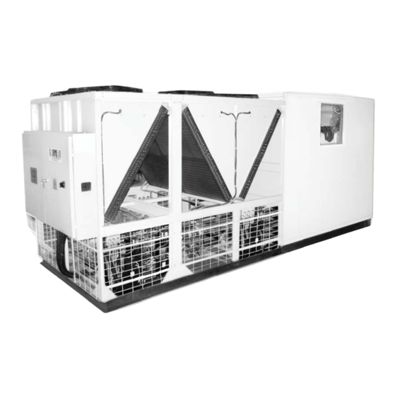
- Page 1 nstallation, peration & M aintenance anual Packaged Air Conditioners PACV-S...
-
Page 2: Table Of Contents
Table of Contents Introduction Nomenclature ....5 Safety Instructions ....5 Specifi c Hazards. - Page 3 Bearing ..... . 32 Fan Belt Adjustment....33 Fan Pulley Adjustment (For variable pitch pulleys only) .
-
Page 4: Introduction
What makes PACV-S series the pride of SKM products is the use of : •... -
Page 5: Nomenclature
INSTALLATION, OPERATION & MAINTENANCE Refer product name plate, wiring diagrams and catalogues Nomenclature for the electrical characteristic, of the equipment to select correct wire sizes and isolators prior to the insulation. PAC V - 5 1 008 S Y It is the responsibility of the user or the person installing Power Supply Code the equipment to provide proper grounding and branch Packaged Air... -
Page 6: Points To Remember
INSTALLATION, OPERATION & MAINTENANCE • remove guards Points To Remember during operation. • Do not wear loose-fi tting Being an electromechanical machine, the unit may fail or clothing when working cause diffi culties. Remembering the following few points will near rotating shafts and ensure correct and prompt rectifi... -
Page 7: Component Features
SKM PACV-S series, all models, are restricted to a 14FPI (1.8 limited warranty. mm) fi n spacing condenser coil. Gulf dust storms and the general level of available maintenance in Gulf countries ensures this condenser coil design shall provide long life and maintenance... - Page 8 The cross wave fi ns and staggered tubes design uses the PACV-S series can be with a range of fi lter sections and fi lters evaporator surface effectively by creating uniform to meet requirements for the most demanding applications.
-
Page 9: Liquid Line Controls
B117. The entire casing panels are designed to be leak proof Sight glass against rain and ensure rain cannot enter the PACV-S series Used to observe the fl ow of liquid refrigerant. Bubbles or packaged air conditioner interior. Evaporator section sealed foaming in the sight glass indicate a shortage of refrigerant or by the use of vinyl gasketing material. -
Page 10: Electrical Control Panel
Microprocessor Controller Factory settings for pressure switches and Fan cycling All PACV-S series package units are equipped with a full function microprocessor based controller as a standard feature. The controller is factory programmed for the control of evaporator Factory Switch Settings fan, compressors and condenser fans. -
Page 11: Room Unit
INSTALLATION, OPERATION & MAINTENANCE Display Information Room unit display (Operator Controls) SKM Pacvs series package units offer LCD display which allows the operator to access different parameters of the unit. Operator can view and change the unit parameters. The display information includes: •... - Page 12 INSTALLATION, OPERATION & MAINTENANCE Step One: Location and Mounting Select a mounting location with good air circulation away from ventilation inlets, doors, windows, or other fresh air entry points or near direct heat sources. For room installation, the room unit should be mounted at least 4-1/2 feet above the fl...
-
Page 13: Installation
INSTALLATION, Receiving of Equipment Handling • Rigging holes are provided on the sides of the unit. Responsibility should be assigned to a • Avoid twisting or uneven lifting of the unit dependable individual at the job site to • The cable length from bracket to the hook should always receive material. -
Page 14: Storage
INSTALLATION, Single Unit Installation Storage SPACING FOR SERVICE When the PACV-S units need to be stored in a prolonged period prior to installation, the following protective measures are required: • Units must be stored in a protected area and safe from construction debris. Do not remove the wooden coil guard. -
Page 15: Pre-Installation Checkup
INSTALLATION, Multiple Units Installation (Modular • If there are walls on one or two adjacent sides of the unit. Construction) The walls may be of any height. If there are walls on more than two adjacent sides of the unit. The walls should not be higher than the unit. -
Page 16: Preparation For Installation
OPERATION Preparation For Installation Carrying Out Installation Unpack the unit carefully. When deciding on the location of the unit with the Unfasten or dismantle transport locks. owner, the following restrictions must be taken into consideration: Packing material to be fully removed and disposed. The unit base frame must be fi... -
Page 17: Pre-Startup Checklist
OPERATION the oil charge has been properly adjusted to maintain the oil level Pre Startup Checklist at the center of the sight glass. • Make sure the power supply voltage and frequency are as given in the unit name plate. •... -
Page 18: Service Record
OPERATION Operational Check-Out Service Record A permanent data sheet should be prepared on each After the system has been charged and has operated for installation, with a copy for the owner and the original for the at least two hours at normal operating conditions without installing contractor’s fi... -
Page 19: Unit Startup
OPERATION module (if available in compressor) are healthy. Unit Start Up • If above are satisfi ed, solenoid valve will be opened • Switch on the three phase power supply to the unit. and when the low pressure switch closes, compressor •... -
Page 20: Display & Keypad Operation
OPERATION Display and Keypad operation If supply fan is not starting, navigate to these screens to fi nd out the reason. In order for the supply fan to start, the Run/Stop input should be “Run”, Room Unit should be “On”, Schedule Status should be “On”... -
Page 21: Alarms
OPERATION Factory parameters will show Compressor Minimum off • Below Screen will appear. time, Compressor Minimum On time, Low pressure alarm delay, Cooling step, Cooling Differential, Condenser Stage1 On pressure, Condenser Stage1 Off pressure, Condenser On Differential pressure, Condenser Off Differential pressure, Schedule enable/disable, Clearing alarm history and software BSP version of the controller. -
Page 22: Operation Of The Room Unit
OPERATION protector module senses a high internal temperature Operation of the Room Unit in the compressor. When this happens, corresponding The room unit displays indoor temperature (duct temperature if circuit will be switched off and alarm will be generated. optional duct sensor is used), temperature set point, unit on/off This alarm is automatic reset as standard. -
Page 23: Switching In And Switching Off The Unit
OPERATION • Press “plus button” multiple times to reach parameter 005. At this stage parameter 005 Switching on and switching off the unit will be blinking. On pressing “mode button”; Press the button to make the unit on and off. When the unit is parameter value will start blinking. - Page 24 OPERATION • After the year is confi rmed, it will jump to the view of month follows in 24-hour time format: and day. The view is showed as follows: • After the time format is confi rmed, HMI-SG will jump to the view of year.
-
Page 25: Commissioning Test Report
OPERATION Table 5 | 25... -
Page 26: Maintenance
MAINTENANCE Periodic Maintenance Following Checklist describes the suggested maintenance schedule to maintain proper operation of the unit. Detailed procedures are mentioned in the corresponding pages. Component Checklist Weekly Monthly Half Yearly Annually General Check for Corrosion and Repaint as Necessary Check amperage draw on blower motor Check condensate line... - Page 27 MAINTENANCE Apply heat evenly over the length and circumference of the Maintenance joint to draw the brazing material into the joint by capillary action. Remove the brazing rod and fl ame from the joint as The maintenance of this equipment shall be in accordance soon as a complete fi...
-
Page 28: Leak Testing, Evacuation
MAINTENANCE Using OFN (oxygen free nitrogen) during Leak Testing, Evacuation & Charging brazing: Procedures: All pipe work shall be cut square with a proprietary pipe The below mentioned procedures are to be followed whenever cutter to give a clean cut, without copper fragmentation. any major repair or replacement is done on the system. - Page 29 MAINTENANCE Pressurise the system using Nitrogen to the below mentioned Leak testing procedure pressures based on the refrigerant being used in the system. If there is any residual refrigerant left in the system this must be recovered prior to follow this procedure. Maximum Maximum Refrigerant...
- Page 30 MAINTENANCE Triple Evacuation Method A vacuum pump capable of pumping down to 500 microns should be connected to both the low and high side evacuation valves with Copper tube or high vacuum hoses (¼” ID minimum). If the compressor has service valves, they should be opened. Operate pump to bring down the system pressure to 1500 microns and continue operating for another 10 minutes.
- Page 31 MAINTENANCE and connect it to the low side. Now with the compressor running, Refrigerant charging open the cylinder valve, purge the refrigerant and charge the The proper performance of air conditioning system is system until the weight of dependent on the proper refrigerant charge. An under- refrigerant charged is equal to charged system will starve the evaporator, resulting that mentioned on the name...
-
Page 32: Fan
MAINTENANCE Replacement instructions of fan bearings assembled on Cast iron pillow blocks For smooth operation fan must be serviced • Unlock the casing cover easing screws at both sides. Using regularly. The most important maintenance appropriate tools, hold the shaft in an appropriate position measures to be made at least twice a year are: in order not to damage the inlet funnel or rotors wheel. -
Page 33: Fan Belt Adjustment
MAINTENANCE When installing new belts or during replacement, do not stretch Cleaning them over the sheaves; Instead loosen the adjustable motor To ensure the motor operates correctly, remove mounting base. Once the new belts are installed, adjust the belt any dust or foreign bodies which might clog the tension using tension gauge. - Page 34 MAINTENANCE Excessive belt tension shortens belt • Never mix new and used belts on a life and may cause bearing & shaft drive. damage • Never mix belts from more than one manufacturer. Note: When new belts are installed on a drive, •...
-
Page 35: Fan Pulley Adjustment (For Variable Pitch Pulleys Only)
MAINTENANCE The adjustments are to be done only in half turn adjustments. Once the adjustments have been made, replace the external key and tighten the adjustment set screw. The belt may now be installed and the belt tension adjusted by using the adjustable motor mounts. Measure the RPM and the motor current drawn and record the change in current and RPM. -
Page 36: Mold In And Around Drain Pans
Dirt collects in the line . Duct Connections Drain line is clogged. Connections of supply and return ducting to the PACV-S series Pan can over fl ow. packaged units should be by means of fl exible duct connections to prevent any vibrations being transmitted to the ducting. It must Possibility of mold growing. -
Page 37: Coil
MAINTENANCE to the manufacturer’s instructions. If desired, heat the Coil solution to 150° F maximum to improve its cleaning capability. If the coil is to deliver its full cooling or heating capacity both its internal and external surfaces must be clean. Pour the cleaning solution into the sprayer. -
Page 38: Dismantling & Disposal
MAINTENANCE . After running the replacement Warning: Dis- compressor for a minimum of 10 minutes, Disposal of fi lter drier cores, compressor shut down the compressor and drain excess oil and system components should be oil from the Schrader valve until the oil level handled according to local laws. - Page 39 MAINTENANCE Warning: Don’t place open fl ame near or on bulb Bulb locations Figure 24. Figure 27. Valve Orientation Solder techniques Figure 25. Figure 28. Bulb and external equalizer locations Figure 26. | 39...
-
Page 40: Hot Gas Bypass
MAINTENANCE • Hot Gas Bypass On many air conditioning and refrigeration systems it Brazing Procedures is desirable to limit the minimum evaporating pressure during periods of low load either to prevent coil icing or Any of the commonly used brazing alloys for high side usage to avoid operating the compressor at a lower suction are satisfactory. - Page 41 MAINTENANCE Service Tips: MALFUNCTION - FAILURE TO OPEN POSSIBLE CAUSE REMEDY 1. Pilot solenoid coil de-energized. 1. Energize solenoid coil. 2. Pilot solenoid coil failure. 2. Replace solenoid coil. 3. External equalizer line pinched shut, plugged or not connected. 3. Connect or replace external equalizer line. 4.
- Page 42 MAINTENANCE Service Tips: VALVE MALFUNCTION CAUSE REMEDY TYPE ADRI-1-1/4 Failure to open 1. Dirt or foreign material in valve 1. Disassemble valve and clean ADRIE-1-1/4 1. Dirt or foreign material in valve 1. Disassemble valve and clean ADRS-2 2. Diaphragm failure 2.
-
Page 43: Refrigerant Recovery, Recycling
MAINTENANCE Voltage are no blockages. Check the voltage across incoming power terminals when • Inspect the evaporator and condenser coils for dirt, bent the system is operating. Voltage requirements are: fi ns, etc. If the coils appear dirty, clean them according to Voltage should not to exceed voltage utilization the instructions described under “Coil Cleaning”. - Page 44 MAINTENANCE • Is conducted whenever technicians need to open or dispose of air conditioning or inlet port) is clean before starting every job. This screen refrigeration equipment. prevents damage to the unit from debris that may get past • Includes removal of refrigerant vapor the inline fi...
- Page 45 MAINTENANCE Figure 33 Push/Pull Recovery Procedure (for Bulk Liquid Figure 34 Refrigerant) Tank Cooling Procedure (Optional) Note: A scale must be In order for this procedure to work, you must have at least 2.3 used avoid kgs. of liquid refrigerant in the storage tank. overfi...
-
Page 46: Trouble Shooting
MAINTENANCE Trouble Shooting Problem: Compressor is Noisy Symptoms • Abnormally cold suction line. Possible Cause • Liquid “Flood back.” Recommended Action • Check and adjust superheat. Check if remote bulb is loosen suction line and refi x. Symptoms • Abnormally cold suction line. Compressor knocks. Possible Cause •... - Page 47 MAINTENANCE Trouble Shooting Problem: Suction pressure Too High Symptoms • Compressor runs continuously. Possible Cause • Excessive load on unit. Recommended Action • Check unit sizing & selection. Investigate system design & install additional air conditioning if required. Symptoms • Abnormally cold suction line.
- Page 48 Trouble Shooting Problem: Supply Fan does not Start Symptoms • Supply Fan Does not start even if unit controller is ON. Possible Cause • Supply fan switched off by unit controller due to motor overload trip, or voltage monitor trip, or room unit communication loss. Recommended Action •...
-
Page 49: Loading Points
APPENDIX- I Loading Points LOADING POINTS TOTAL PACV- UNIT WEIGHT 1049 51008-S 1154 51010-S 2050 51014-S 2208 52015-S 1001 2175 51017-S 2254 52017-S 1023 2395 52020-S 1086 2553 52023-S 1158 3133 52026-S 1421 3228 52030-S 1464 3248 52032-S 1473 1011 1008 3648 52038-S... - Page 50 Loading Points LOADING POINTS TOTAL PACV- UNIT WEIGHT 1004 1360 1357 4708 52050-S 2135 1153 1134 1391 1378 5056 52055-S 2294 1026 1284 1284 7720 52065-S 3502 1046 1030 8758 53070-S 3973 1148 1105 9149 53075-S 4150 1156 1112 9316 53080-S 4226 1210...
-
Page 51: Dimensional Data
Dimensional Data APPENDIX- II PACV Models: 51008 S, 51010 S & 61009 S, 61012 S [254] [254] L E G E N D 7 -CONDENSER FAN 6 -CONTROL PANEL 5 -CONDENSER COIL 4 -COMPRESSOR 3 -FAN MOTOR 2 -EVAPORATOR FAN ACCESS 1 -EVAPORATOR COIL CERTIFIED DRAWINGS ARE... - Page 52 Dimensional Data PACV Models: 52026 S to 52038 S & 62033 S to 62046 S DIMENSIONS ARE IN INCHES [mm] [254] [254] MODEL PACV- 52026 S 72.87 15.91 18.54 52.28 8.54 60.63 62033 S [1851] [2946] [1016] [1016] [1540] [404] [471] [1328] [217]...
- Page 53 Dimensional Data PACV Models: 52065 S & 62076 S 108.5 [70] [2756] [70] CERTIFIED DRAWINGS ARE AVAILABLE ON REQUEST ACCESS [254] [508] [254] [5029] [51] [2235] [51] [2896] [2134] 39.31 35.35 39.31 [999] [898] [999] FILTERED VENTILLATION ON BOTH SIDES CABLE ENTRY ACCESS RIGGING HOLES...
- Page 54 PACV Models: 54100 S to 54125 S & 64120 S to 64145 S [70] [70] DIMENSIONS ARE IN INCHES [mm] MODEL PACV- L E G E N D 54100 S 311.2 128.5 44.76 10 -FLEXIBLE CONNECTION 64120 S [7904] [3404] [3264] [1137] 9 -WEATHER PROOF CANOPY...
-
Page 55: Refrigerant Piping Layout
APPENDIX- III Refrigerant Piping Layout This section presents the unit refrigerant piping diagrams for different available confi gurations. Figure 45 Figure 44 APPENDIX- IV Typical Piping Layout Typical Liquid Line Piping Figure 46. | 55... - Page 56 Typical Suction & Discharge Line Piping for Individual Compressor Figure 47 Typical Suction & Discharge Line Piping for Tandem Compressor Figure 48 56 |...
-
Page 57: Filter Dimension
APPENDIX- V Filter Dimensions e s o s & S es FLAT FILTER VEE FILTER BAG FILTER [25] [142] [25] [660] [25] [660] FLAT FILTER VEE FILTER BAG FILTER MODEL PACV-S SIZE H x L QTY. SIZE H x L QTY. -
Page 58: Spare Parts
APPENDIX- VI Spare Parts 58 |... - Page 59 APPENDIX- VII Electrical Data POWER SUPPLY 380-415V/3Ph/50Hz Unit Characteristic Model Compressor Condenser Fan Motor Evaporator Fan Motor PACV-S 19.2 51008 19.2 51010 35.6 51014 1 + 1 22 + 22 118 + 118 35.6 52015 45.6 51017 1 + 1 30 + 22 174 + 118 45.6...
- Page 60 Electrical Data POWER SUPPLY 380V/3Ph/60Hz Unit Characteristic Compressor Condenser Fan Motor Evaporator Fan Motor Model 18.9 61009 61012 61018 1 + 1 24 + 24 145 + 145 62018 44.3 61020 1 + 1 37 + 24 196 + 145 44.3 62020 1 + 1...
- Page 61 Electrical Data POWER SUPPLY 220V/3Ph/60Hz Unit Characteristic Compressor Condenser Fan Motor Evaporator Fan Motor Model 32.6 61009 43.3 61012 16.7 10.9 58.7 61018 1 + 1 47 + 47 245 + 245 16.7 10.9 58.7 62018 16.7 14.4 76.5 61020 1 + 1 60 + 47 340 + 245...
-
Page 62: Typical Wiring Diagram
APPENDIX- VIII Typical Wiring Diagram 62 |... -
Page 63: Instructions For Downloading/Upgrading The Software For Microprocessor
APPENDIX- IX Instructions For Downloading/Upgrading The Software For Microprocessor • Switch off the controller • Insert the SD-Card in the slot • Push the Service-Button • Use a paper clip (feel the click) • Don’t press too strong, you could damage the button •... -
Page 64: P-T Chart
APPENDIX- X P-T Chart ºF ºC R-22 R-410A R-407C R134a ºF ºC R-22 R-410A R-407C R134a ºF ºC R-22 R-410A R-407C R134a -51.1 *11.9 *0.9 *16.0 *21.6 -11.1 34.8 65.4 29.0 13.2 42.0 71.5 123.6 64.6 37.0 -48.3 *9.2 *13.7 *20.2 -10.6 35.8... - Page 65 Manual# : 088- IOM- 2014 Supersedes Manual# : 088- IOM- 2012...
Need help?
Do you have a question about the PACV-S Series and is the answer not in the manual?
Questions and answers