
Subscribe to Our Youtube Channel
Related Manuals for RF Technology Eclipse2 VHF

Summary of Contents for RF Technology Eclipse2 VHF
- Page 1 Eclipse2 VHF / UHF / 800MHz Base Station Technical Manual Publication Reference – TPR-0305920015 Issue 1.5 – June 2009. Eclispe2 Technical Manual V1.5...
- Page 2 Due to our policy of continuous improvement of our products and services, technical specifications and claims that were correct at time going to print maybe subject to variation without notice. RF Technology has endeavoured to ensure that the information in this document is correct and fairly stated, but does not accept liability due to typographical, omissions or other errors or subsequent modifications of the product.
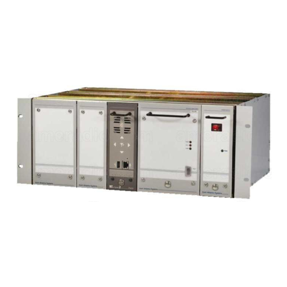
- Page 3 PART 1: INTRODUCTION The Eclipse2 series is a new generation base station developed by RF Technology. The design is based on the software defined radio (SDR) technology which allows user to upgrade their base stations from standard FM modulation to P25 or other digital protocols without hardware changes.
-
Page 4: Operating Basics
PART 2: TRANSCEIVER 2.1 OPERATING BASICS The transceiver will need approximately 40 seconds to boot up after power up. When the transceiver is ready to operate, a voice report (if enabled) can be heard from front panel speaker, and Digital/Analog LED will indicate that the transceiver current working mode. -
Page 5: Rear Panel Connectors
Down – Press this button to decrease the speaker volume Left – Press this button to change channel to next lower programmed number Right – Press this button to change channel to next higher programmed number Reset – The reset switch mounted inside base station, used for reset the transceiver without power cycle, use a small pin (e.g. - Page 6 Line output + Output: balanced 600ohm, 300 to 3000Hz, -20dbm to +10dbm Line output - Output: balanced 600ohm, 300 to 3000Hz, -20dbm to +10dbm GPS 1 pulse/sec input Input: +3.3V to +15V TTL logic Monitor speaker output Output: unbalanced 8 ohm 300 to 3000Hz, 3 Watt maximum System serial bus, Data in Input: +3.3V TTL logic...
-
Page 7: Programming And Monitoring
Table2: RJ45 E/M Line Connector signals 2.2 PROGRAMMING AND MONITORING Programming and monitoring is most easily accomplished with RF Technology’s Service Kit software. This software is based on Java platform and can be run under various operation systems on the host PC, it provides a number of additional useful facilities for the base station configurations. -
Page 8: Connecting With Ethernet
2.2.1 Connecting with Ethernet Ethernet is the most powerful interface of the base station, especially for remote monitoring and controlling via Internet. Each base station has a unique IP address, to connect, the host PC must be in the same sub net with the base station. 2.2.2 Connecting with USB The front-panel USB connector can be also used for connecting to host PC, the operation system need a proper driver to recognize the base station. - Page 9 The 10/100Mbps Ethernet Physical Layer single chip transceiver (U10) provides the interface between RISC processor and the Ethernet. A serial ATA cable is used for connecting between the Master board and System interface board. The DSP (U2) is a 32-bit fixed-point digital signal processor, it provides the base band processing such as: modulation, demodulation, RSSI/SINAD calculation, sub-tone encoding/decoding and audio processing of the base station.
- Page 10 shifted by the bias circuit which is controlled by the RISC processor to give the maximum dynamic range for the ADC. The CODEC has two identical channels, the output of channel 1 is used for line output. PCM signal from the DSP is decoded to analog audio, and amplified, buffered by op- amplifier U10, coupling through the line matching transformer (T2), and sent to the RJ45 E/M Line connector and the D25 system connector.
- Page 11 The Interface board accepts both TTL PTT input and E/M signaling, the TTL PTT is buffered by Q4,Q5, E/M signal is isolated by Opto-coupler U3 to system I/O level. The output of the RISC I/O logic is buffered by U1,Q1-Q3 for interfacing the external logic. The solid-state relay Opto-coupler is used to isolate the system I/O from E/M signal.
- Page 12 2.3.3.1 TX module The TX module can be divided into the VCO, PLL, PA and the Data storage section. The Voltage Controlled Oscillator (VCO) The Voltage Controlled Oscillator uses a junction FET (Q2) which oscillates at the required transmitter output frequency. Varactor diodes (D2, D9, D10, and D11) are used by the PLL and bias control circuits to keep the oscillator on the desired frequency.
- Page 13 A two-pole voltage tuned filter (D6, D7, L18-20, L23 and L24) is used to limit the RF bandwidth prior to the RF amplifier transistor Q1. The tuning voltage is supplied by the RISC processor through the bias control. The circuit values are chosen so that the centre frequency tracks the VCO bias voltage.
-
Page 14: Field Alignments
TX/RX and tone frequency combination. 2.5.1.3 Channel Programming The channel information is stored in Flash memory and can be programmed via the Ethernet, USB or RS232 interface using a Host PC and RF Technology’s Service Kit software. 2.5.1.4 Channel Selection Channel can be select by Service Kit or front panel buttons (if enabled). -
Page 15: Electronic Specifications
2.5.3 Electronic Specifications: 2.5.3.1 Overall Frequency Range: VHF model, 150MHz to 174MHz UHF model, 400MHz to 520MHz 800MHz model, 800MHz to 940MHz Channel spacing: 12.5kHz / 25kHz External reference: 5MHz / 10MHz/ 12.8MHz Monitor speaker output: 3 watts @ 8 ohm Microphone input: 6 mV RMS @200 ohm Duty cycle:... - Page 16 Audio Response: 300Hz to 3000Hz +1/-3dB, Flat or 6dB per Octave de-emphasis Audio Distortion: < 3% Line input level: -20dbm to +10dbm @600ohm 2.5.4 Connectors 2.5.4.1 Antenna Connector Receiver: 50ohm BNC Female Mounted on the module rear panel Exciter: 50ohm N type Female Mounted on the module rear panel 2.5.4.2 Power &...
-
Page 17: Part List
2.6 PART LIST The part reference of 2.6.1 Processor (Master) board 2.6.2 Interface Main Board 2.6.3 TX module 2.6.4 RX module PART 3: POWER AMPLIFIER Eclispe2 Technical Manual V1.5...
Need help?
Do you have a question about the Eclipse2 VHF and is the answer not in the manual?
Questions and answers