Table of Contents
Advertisement
Quick Links
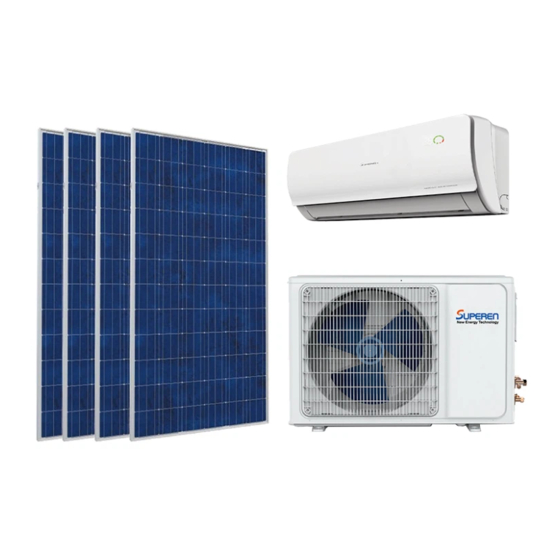
SPLIT-TYPE SOLAR AIR CONDITIONER
Installation Manual
ACDC Hybrid Series
HYBRID-ACDC12-EU/US
HYBRID-ACDC18-EU/US
HYBRID-ACDC24-EU/US
IMPORTANT NOTE:
Read this manual carefully before installing
or operating your solar air conditioner
unit. Make sure to save this manual for
further reference.
CS78421-548-754
Advertisement
Table of Contents

Subscribe to Our Youtube Channel
Related Manuals for Superen HYBRID-ACDC12-EU/US

Summary of Contents for Superen HYBRID-ACDC12-EU/US
- Page 1 SPLIT-TYPE SOLAR AIR CONDITIONER Installation Manual ACDC Hybrid Series HYBRID-ACDC12-EU/US HYBRID-ACDC18-EU/US HYBRID-ACDC24-EU/US CS78421-548-754 IMPORTANT NOTE: Read this manual carefully before installing or operating your solar air conditioner unit. Make sure to save this manual for further reference.
-
Page 2: Table Of Contents
Table of Contents Installation Manual Safety Precautions ........4 Accessories ..........6 ..Installation Summary - Indoor Unit ..........10 Unit Parts ..11 Indoor Unit Installation 1. Select installation location ......11 2. Attach mounting plate to wall ....12 3. - Page 3 Refrigerant Piping Connection ..25 A. Note on Pipe Length ............. 25 B. Connection Instructions –Refrigerant Piping ....25 1. Cut pipes ................25 2. Remove burrs ..............26 3. Flare pipe ends ..............4. Connect pipes ..............27 ....... 29 Air Evacuation 1.
-
Page 4: Safety Precautions
Safety Precautions Read Safety Precautions Before Installation Incorrect installation due to ignoring instructions can cause serious damage or injury. The seriousness of potential damage or injuries is classified as either a WARNING or CAUTION. This symbol indicates that ignoring instructions may cause death or serious injury. - Page 5 WARNING 6. For all electrical work, follow all local and national wiring standards, regulations, and the Installation Manual. You must use an independent circuit and single outlet to supply power. Do not connect other appliances to the same outlet. Insufficient electrical capacity or defects in electrical work can cause electrical shock or fire.
-
Page 6: Accessories
Accessories The air conditioning system comes with the following accessories. Use all of the installation parts and accessories to install the air conditioner. Improper installation may result in water leakage, electrical shock and fire, or cause equipment failure. Name Shape Quantity Mounting plate Clip anchor... - Page 7 Air freshening filter Seal Optional Parts Drain joint SPLIT-TYPE SOLAR AIR CONDITIONER Owner’s Manual ACDC Hybrid Series HYBRID-ACDC12-EU/US HYBRID-ACDC18-EU/US HYBRID-ACDC24-EU/US Owner’s manual CS78421-548-754 IMPORTANT NOTE: Read this manual carefully before installing or operating your new air conditioning unit. Make sure to save this manual for future reference.
-
Page 8: Installation Summary - Indoor Unit
Installation Summary - Indoor Unit 15cm (5.9in) 12cm 12cm (4.75in) (4.75in) 2.3m (90.55in) Select Installation Location Determine Wall Hole Position (Page 11) (Page 12) Attach Mounting Plate Drill Wall Hole (Page 12) (Page 12) Page 8... - Page 9 Connect Piping Connect Wiring Prepare Drain Hose (Page 25) (Page 17) (Page 14) Wrap Piping and Cable (Page 18) STEP Mount Indoor Unit (Page 18) Page 9...
-
Page 10: Unit Parts
Unit Parts Wall Mounting Plate Front Panel Louver Drainage Pipe Power & Signal Cable Refrigerant Piping Remote Control (Some Units) Remote Holder Outdoor Unit Solar Input (DC100-300V) Powe Cable (AC 220-240V) Fig. 3.1 CAUTION Use a stud finder to locate studs to prevent unnecessary damage to the wall. Copper pipe must be insulated independently. -
Page 11: Indoor Unit Installation
Indoor Unit Installation DO NOT install unit in the following Installation Instructions – Indoor locations: Unit Near any source of heat, steam, or combustible gas PRIOR TO INSTALLATION Near flammable items such as curtains or Before installing the indoor unit, refer to the clothing label on the product box to make sure that the model number of the indoor unit matches the... -
Page 12: Attach Mounting Plate To Wall
Refer to the following diagram to ensure proper distance from walls and ceiling: 15cm (5.9in) or more 12cm (4.75in) 12cm (4.75in) or more or more Fig. 4.1 2.3m (90.55in) or more Step 2: Attach mounting plate to wall Step 3: Drill wall hole for connective piping The mounting plate is the device on which you You must drill a hole in the wall for refrigerant will mount the indoor unit. - Page 13 Wall Indoor Outdoor Φ55 Φ55 HYBRID-ACDC12-EU/US Fig.3.2 Fig. 4.2 MOUNTING PLATE DIMENSIONS Different models have different mounting plates. In order to ensure that you have ample room to mount the indoor unit, the diagrams to the right show different types of mounting plates along...
-
Page 14: Prepare Refrigerant Piping
Step 4: Prepare refrigerant piping 3. Use scissors to cut down the length of the insulating sleeve to reveal about 15cm (6in) The refrigerant piping is inside an insulating of the refrigerant piping. This serves two sleeve attached to the back of the unit. You must purposes: prepare the piping before passing it through the •... -
Page 15: Connect Drain Hose
Step 5: Connect drain hose PLUG THE UNUSED DRAIN HOLE By default, the drain hose is attached to the left- To prevent unwanted leaks you must plug hand side of unit (when you’re facing the back the unused drain hole with the rubber plug of the unit). - Page 16 BEFORE PERFORMING ELECTRICAL WORK, READ THESE REGULATIONS 1. All wiring must comply with local and national electrical codes, and must be installed by a licensed electrician. 2. All electrical connections must be made according to the Electrical Connection Diagram located on the panels of the indoor and outdoor units. 3.
-
Page 17: Connect Signal Cable
Step 6: Connect signal cable TAKE NOTE OF FUSE SPECIFICATIONS The signal cable enables communication between The air conditioner’ s circuit board (PCB) is the indoor and outdoor units. You must first designed with a fuse to provide overcurrent choose the right cable size before preparing it for protection. -
Page 18: Wrap Piping And Cables
6. Feed the signal wire through this slot, from DO NOT INTERTWINE SIGNAL CABLE WITH the back of the unit to the front. OTHER WIRES 7. Facing the front of the unit, match the wire While bundling these items together, do not colors with the labels on the terminal block, intertwine or cross the signal cable with any connect the u-lug and firmly screw each... - Page 19 3. Connect drain hose and refrigerant piping If refrigerant piping is already embedded in (refer to Refrigerant Piping Connection the wall, do the following: section of this manual for instructions). 1. Hook the top of the indoor unit on the upper 4.
-
Page 20: Outdoor Unit Installation
Outdoor Unit Installation Installation Instructions – Outdoor Unit Step 1: Select installation location Before installing the outdoor unit, you must choose an appropriate location. The following are standards that will help you choose an appropriate location for the unit. Proper installation locations meet the following standards: ... -
Page 21: Install Drain Joint
If the drain joint comes with a rubber seal SPECIAL CONSIDERATIONS FOR EXTREME (see Fig. 5.4 - A ), do the following: WEATHER 1. Fit the rubber seal on the end of the drain joint If the unit is exposed to heavy wind: that will connect to the outdoor unit. - Page 22 The following is the outdoor unit sizes and the distance between the mounting feet. Prepare the installation base of the unit according to the dimensions below. Fig. 5.5 HYBRID-ACDC12-EU/US HYBRID-ACDC18-EU/US HYBRID-ACDC24-EU/US 8. Using a wrench, tighten each nut until snug.
-
Page 23: Connect Signal And Power Cables
If you will install the unit on a wall-mounted BEFORE PERFORMING bracket, do the following: ELECTRICAL WORK, READ THESE REGULATIONS 1. All wiring must comply with local and CAUTION national electrical codes, and must be Before installing a wall-mounted unit, make installed by a licensed electrician. - Page 24 PA Y ATTENTION TO LIVE WIRE WARNING While crimping wires, make sure you clearly BEFORE PERFORMING ANY ELECTRICAL distinguish the Live (“L”) Wire from other wires. OR WIRING WORK, TURN OFF THE MAIN POWER TO THE SYSTEM. WARNING 1. Prepare the cable for connection: ALL WIRING MUST PERFORMED STRICTLY USE THE RIGHT CABLE IN ACCORDANCE WITH THE WIRING...
-
Page 25: Refrigerant Piping Connection
Refrigerant Piping Connection Note on Pipe Length The length of refrigerant piping will affect the performance and energy efficiency of the unit. Nominal efficiency is tested on units with a pipe length of 5 meters (16.5ft). Refer to the table below for specifications on the maximum length and drop height of piping. Maximum Length and Drop Height of Refrigerant Piping per Unit Model Model Capacity... -
Page 26: Remove Burrs
DO NOT DEFORM PIPE WHILE CUTTING Flare nut Be extra careful not to damage, dent, or deform the pipe while cutting. This will drastically reduce the heating efficiency of the unit. Copper pipe Step 2: Remove burrs Burrs can affect the air-tight seal of refrigerant piping connection. -
Page 27: Connect Pipes
6. Place flaring tool onto the form. Instructions for Connecting Piping to 7. Turn the handle of the flaring tool clockwise Indoor Unit until the pipe is fully flared. 1. Align the center of the two pipes that you will 8. - Page 28 Instructions for Connecting Piping to USE SPANNER TO GRIP MAIN Outdoor Unit BODY OF VALVE Torque from tightening the flare nut can snap 1. Remove protective caps from ends of valves. off other parts of valve. 2. Align flared pipe end with each valve, and tighten the flare nut as tightly as possible by hand.
-
Page 29: Air Evacuation
Air Evacuation Preparations and Precautions Evacuation Instructions Air and foreign matter in the refrigerant circuit Before using the manifold gauge and vacuum can cause abnormal rises in pressure, which pump, read their operation manuals to familiarize can damage the air conditioner, reduce its yourself with how to use them properly. -
Page 30: Note On Adding Refrigerant
ADDITIONAL REFRIGERANT PER PIPE LENGTH Connective Pipe Air Purging Additional Refrigerant Length (m) Method < Standard pipe length Vacuum Pump HYBRID-ACDC12-EU/US HYBRID-ACDC18-EU/US HYBRID-ACDC24-EU/US R410A R410A > Standard pipe Vacuum Pump (Pipe length – standard length) x 20g/m (Pipe length –... - Page 31 Electrical and Gas Leak Checks WARNING – RISK OF Electrical Safety Checks ELECTRIC SHOCK After installation, confirm that all electrical wiring is installed in accordance with local and national ALL WIRING MUST COMPLY WITH LOCAL AND regulations, and according to the Installation NATIONAL ELECTRICAL CODES, AND MUST BE Manual.
- Page 32 Installation of the Solar Photovoltaic System This manual contains information regarding the installation and safe handling of solar photovoltaic module. All instructions should be read and understood before attempting to install. If there is any question, please contact our sales department for further explanation. The installer should conform to all the safety precautions listed in this guide when installing the module.
- Page 33 Photovoltaic solar modules convert light energy When installing the system, abide with all local, to direct-current electrical energy. They are regional and national statutory regulations. designed for outdoor use. Solar modules can be Obtain a building permit where necessary. Abide ground, roof, vehicles, or boat roof mounted.
- Page 34 Keep children well away from the system while Use only insulated tools that are approved for transporting and installing mechanical and working on electrical installations. electrical components. Fig. 9.7 Fig. 9.10 Completely cover the module with an opaque When performing installation in dry conditions, material during installation to keep electricity please ensure the tools used in the dry.
- Page 35 The module frame must be properly grounded. Do not mount module near the place where the The grounding wire must be properly fastened flammable gas may be generated or collected. to the module frame to assure good electrical contact. Use the recommended type, or an equivalent, connector for this wire.
- Page 36 When installing module on a roof, ensure that 3. Ground mounting the roof construction is suitable. In addition, any Select the height of the mounting system to roof penetration required to mount the module prevent the lowest edge of the module from must be properly sealed to prevent leaks.
- Page 37 Do not stand or step on module. 3. Ground mounting Module mounting must use the pre-drilled mounting holes in the frame. The most common mounting is achieved by mounting the module using the four symmetry points closed to the inner side of the module frame.
- Page 38 are not the specified brand of the manufacturer, Electrical Installation it must comply with the electrical requirement. The cross section area of cable and the capacity 1. General installation of connector must be selected to suit the Do not use modules of different configurations maximum system short circuit current.
- Page 39 The protecting sheath must be used on the cable The cable can resist UV rays and climate of rapid if there is a possibility of children or animals change. touch it easily. The rated voltage of the cable is more than 600V. The cross-section area of the cable depends on the maximum short circuit current and the length of wire.
- Page 40 secure the entire assembly. The spring washer is If the support frame is made of metal, the surface required in order to prevent screw loosening and of the frame must be electroplated and have cause improper grounding. excellent conductivity. The grounding wire must be fastened to the support frame properly.
- Page 41 GROUNDING PRINCIPALS Equipment grounding provides protection from shock caused by a ground fault and is required for all PV systems by the NEC. A ground fault occurs when a current-carrying conductor comes into contact with the frame or chassis of an appliance or an electrical box. A person who touches the frame or chassis of the faulty appliance will complete the circuit and receive a shock.
- Page 42 Test Run List of Checks PASS FAIL TEST Before Test Run to Perform (√) (×) RESULT Only perform test run after you have completed Solar array Voc test the following steps: Solar array grounding • Electrical Safety Checks – Confirm that fault test the unit’...
- Page 43 DOUBLE-CHECK PIPE CONNECTIONS During operation, the pressure of the refrigerant circuit will increase. This may reveal leaks that were not present during your initial leak check. Take time during the Test Run to double-check that all refrigerant pipe connection points do not have leaks. Refer to Gas Leak Check section for instructions.
- Page 44 European Disposal Guidelines This appliance contains refrigerant and other potentially hazardous materials. When disposing of this appliance, the law requires special collection and treatment. Do not dispose of this product as household waste or unsorted municipal waste. When disposing of this appliance, you have the following options: •...
- Page 45 The design and specifications are subject to change without prior notice for product improvement. Consult with the sales agency or manufacturer for details. Version: SA/SPE ACDC IM 01JUL2019. V1.1...
Need help?
Do you have a question about the HYBRID-ACDC12-EU/US and is the answer not in the manual?
Questions and answers