Advertisement
Quick Links
TABLE OF CONTENTS:
Notes for Receiving Freight
Installation Documents
•
Workbench
•
Tech Gallery
•
Glass Wall
•
Communication Wall
•
Tech Bench
Cleaning & Maintenance Guides
Warranty & Manufacturer Contact Information
•
Replacement Cabinet Lock/Key
uBreakiFix Fixture Install & Maintenance Guide
TOOLS REQUIRED:
•
Cordless Drill
•
1/8" Drill Bit
•
1/2" Drill Bit (Optional 1/2" Paddle Bit)
•
Phillips Driver Bit
•
Tape Measure
•
Level
•
Pencil
•
Flathead Screwdriver
•
Phillips Screwdriver
•
7/16" Wrench
•
7/16" Socket
•
5mm Allen
•
4mm Allen
1
Advertisement

Summary of Contents for Katalyst asurion uBreakiFix Fixture
- Page 1 TABLE OF CONTENTS: TOOLS REQUIRED: Notes for Receiving Freight • Cordless Drill • 1/8” Drill Bit Installation Documents • 1/2” Drill Bit (Optional 1/2” Paddle Bit) • Workbench • Phillips Driver Bit • Tech Gallery • Tape Measure • Glass Wall •...
- Page 2 Any and all shortages or damaged items must be written down on the BOL. Note the item(s) that are visibly damaged or missing on the BOL before you sign it. Then email your representative at Katalyst, or call (816) 221-0121 to report the problem.
- Page 3 • Keep all crating and packaging material with the damaged item(s) for inspection by the company’s claim inspector until told by Katalyst or the carrier to return or dispose of the item(s). • Claims not reported within 7 calendar days may not be honored.
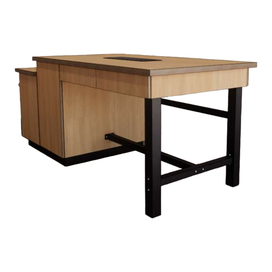
- Page 4 WORKBENCH INSTALLATION (8’ OR 12’ VERSION) PARTS TO ASSEMBLE • Toe Kick • Short Cabinet • Tall Cabinet • Metal Legs (2) • Short Cross Metal Member • Long Cross Metal Member • Countertop • Drawer Assembly (Metabox) • Drop-in Power Trough (Black Box) HARDWARE PROVIDED A.
- Page 5 ASSEMBLING THE BASE CABINETS STEP 1 Place the toekick over the floor electrical and align in the space. Use a screw driver to adjust the leveling feet as necessary. The cross members should go the long direction of the table. STEP 2 Set the short cabinet on to half the toe kick and align with the access openings.
- Page 6 ASSEMBLING THE METAL TABLE BASE STEP 1 Locate the legs, short and long metal cross members. STEP 2 Bolt the short cross member between the legs using the provided carriage bolts (D). STEP 3 Bolt the long cross member onto the middle of the short cross member with provided carriage bolts (E).
- Page 7 COMPLETING THE WORK BENCH ASSEMBLY STEP 1 Place the countertop onto the drawer unit assembly and align with bolt holes below. STEP 2 Insert furniture bolts (I) through the top of the drawer unit assembly into the base of the countertops. Use allen wrench to secure.
- Page 8 12’ TECH GALLERY ASSEMBLY PARTS TO ASSEMBLE • (2) 4’ x 7’ K-Wall Frames • (1) 4’ x 4’ K-Wall Frame • Cabinet • (3) Header Boxes • (2) End Panels • (6) Furring Strips • (12) C-Channel • (3) Bottom Wall Panels •...
- Page 9 PREPARING THE WALL SYSTEM STEP 1 Insert system screws (A) into the following wall elements as applicable: standard wall panels (4 per panel) header box (2 per 4’ segment) cabinets (4 per) wood end plates STEP 2 Lay the two larger K-Wall frames onto a clean and level floor.
- Page 10 INSTALL FURRING STRIPS (2 Furring Strips Per 4’ segment) STEP 7 Insert the c-channel into the furring strips. Hand tighten the bolts (C) until lightly pressing against the c-channel. STEP 8 Put the furring strip with the c-channels into the mounting channel on the K-Wall frames.
- Page 11 CONNECT WALL FRAMES TO THE WALL (These instructions are for gypsum board wall construction. For other wall construction methods, see notes below.) STEP 10 Lift the larger frame sections and push against the wall. STEP 11 While one person holds the frame against the wall, determine the fi...
- Page 12 CONNECT THE CABINET & WALL PANEL STEP 16 Set the cabinet next to the K-Wall Frames mounted on the wall. Use provided hardware (E) to fasten cabinet to the adjacent frame. Adjust leveling feet as needed to level. STEP 17 Set the 4’...
- Page 13 HANG THE WALL PANELS STEP 22 Locate the panel(s) that do not have a slot on the back side. This is the bottom panel. Hang this panel fi rst by sliding the system screws into the keyhole slots. STEP 23 Starting with the side that will have the large panel (poster frame/TV), hang the remaining panels working your way up from the bottom.
- Page 14 GLASS WALL INSTALLATION INSTALL HARDWARE NOTES Assemble glass divider wall using experienced installers aware of all local, state and federal building and structural codes. All fasteners are to be specifi ed by site supervisor. DECORATIVE VINYL NOTES The masking is left on the glass to protect the decorative vinyl fi...
- Page 15 STEP 7 Center the “uBreakiFix” sign template and align the base of the template and level 60” above the floor. STEP 8 Remove the double stick tape from the letters and insert them in the templated spot beginning with the two letter “i”s using the secondary template to locate the dot above the “i”.
- Page 18 Plain or DF Tape Mount Install Instructions Smaller flat cut Letters / Logos Flat, Smooth Interior Surface Small, typically under 6" flat cut letters, interior install. Tools Required: Stencil Guide, level, masking tape, tape measure, cleaning cloth, adhesive and/or VHB tape. 1.
- Page 19 THIS PAGE INTENTIONALLY LEFT BLANK...
- Page 20 COMMUNITY WALL INSTALLATION PARTS TO ASSEMBLE • Unistrut Rails • Portrait TV Shroud (Box Frame) • Landscape TV Shroud (Single or Double) • Messaging Kit (COMING SOON) • TV’s • TV Brackets HARDWARE PROVIDED A. Unistrut Mounting Hardware B. Unistrut Nuts C.
- Page 21 MOUNTING THE SUPPORT FRAMES STEP 1 Locate the unistrut rails. Measure and mark a level line on the wall 58” and 72 1/2” above the fi nished floor. Align the bottom edge of each unistrut rail with each line. STEP 2 Mark holes in the unistrut rails and install Easy Toggl Anchors (A) per instructions below.
- Page 22 MOUNTING THE RED PANELS STEP 6 Mount two “T” brackets per TV into the unistrut track and within the Box Frames. In the portrait box frame, align the right bracket with the notch on the side. The brackets should be 10” apart. STEP 7 Tighten all connections with Box Frames and “T”...
- Page 23 STEP 9 Carefully lift the TV with brackets attach and set over the Notch in the “T” Brackets. Once set, the TV can tip out slightly for maintence and cable connections. STEP 10 Install sign messaging package (COMING SOON) STEP 11 Cut and install Unistrut track cover as needed.
- Page 24 TECH BENCH INSTALL PARTS TO ASSEMBLE • Worksurface • Table Legs STEP 1 Layout the table base components. STEP 2 Thread the metal rod through the base, pipe and into the T leg. STEP 3 Use a wrench to secure the nut onto the end of the metal rod. STEP 4 Use provided hardware to fasten the legs onto the worksurface top.
- Page 25 CLEANING & MAINTENANCE GUIDES FORMICA LAMINATE ORDINARY CLEANING Formica® Laminate is very easy to clean. In most cases, you only need to use a clean, damp, nonabrasive cotton cloth and a mild liquid detergent or household cleaner. Rinse with clean water, using a clean, non-abrasive cotton cloth.
- Page 26 WARRANTY Upon fi nal payment all items provided by Katalyst Group Inc. will receive a one year limited warranty from the date of shipment or of invoice, whichever occurs fi rst. The fi nished product will be free of defects in materials and workmanship.
- Page 27 1701 Vernon Street North Kansas City, MO 64116 O: (816) 221-0121 W: katalyst.group UBIF PROJECT MANAGERS Jason Nelson jasonn@katgroupinc.com Alexis Kiel alexis@katgroupinc.com CONSTRUCTION PROJECT MANAGERS Alexis Kiel alexis@katgroupinc.com FINANCE & ACCOUNTING Katie Fisher offi ce@katgroupinc.com SHIPPING & RECEIVING Lacey Pacheco lacey@katgroupinc.com...
- Page 28 Drawer Assembly, Workbench Short Cabinet, Workbench...
- Page 30 Tech Gallery Panels...
- Page 31 uBreakiFix Fixture Install & Maintenance Guide...
- Page 32 CARE SANITIZER DISPLAY (KATALYST VERSION) STEP 1 Hang the slatwall brackets attached to the display box onto the accessory wall. STEP 2 Hang the product mounting bracket onto the slot roughly centered in the display box. STEP 3 Lift the bracket slightly and slide the slot in the printed graphic over it.
- Page 33 CARE SANITIZER DISPLAY (SHOP DESIGN VERSION) STEP 1 Hang the slatwall brackets attached to the display box onto the accessory wall. STEP 2 Hang the product mounting bracket onto the slot roughly centered in the display box. STEP 3 Lift the bracket slightly and slide the slot in the printed graphic over it.
Need help?
Do you have a question about the asurion uBreakiFix Fixture and is the answer not in the manual?
Questions and answers