Table of Contents
Advertisement
Quick Links
Advertisement
Table of Contents

Summary of Contents for IKA INC 125 FS digital
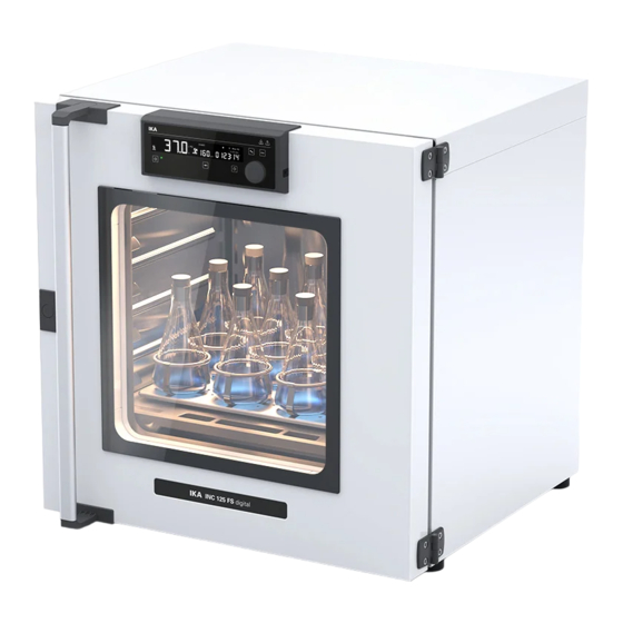
- Page 1 INC 125 FS digital...
- Page 2 ENGLISH...
- Page 3 Fig. 2 Fig. 1...
-
Page 4: Table Of Contents
Explication of warning symbols ��������������������������������������������������������������������7 EN ISO 12100 and DIN 12880� A copy of the complete EU Declaration of Conformity or further declarations of conformity can be Safety instructions ����������������������������������������������������������������������������������������8 requested at sales@ika�com� Intended use ����������������������������������������������������������������������������������������������11 Explication of warning symbols Useful information ������������������������������������������������������������������������������������ 12... -
Page 5: Safety Instructions
/// General Symbols Notice! › Set up the device in a spacious area on an even, stable, clean, non-slip, dry and fireproof A––– Position number surface� › The feet of the equipment must be clean and undamaged� Correct / Result! ›... -
Page 6: Intended Use
› Only use IKA approved accessories� manufacturer� › Use only original IKA spare parts� › if the device is operated improperly or contrary to the manufacture’s specifications� › if the device or the printed circuit board are modified by third parties�... -
Page 7: Useful Information
Useful information /// Material /// Calibration and adjustment This menu shows how the values can be entered after the respective temperatures are The inner chamber of the device is made of high quality stainless steel� The window on the door approached and with an external measuring device cross-checked (calibrated)�... -
Page 8: Unpacking
› For lifting the device, four people are required� › You may get your hands or feet squashed when transporting and setting down the device� Wear protective gloves and safety boots� INC 125 FS digital Hexagon socket offset screw key Shelf... - Page 9 Notice! When lifting the device, do not use the door / door handle� This may damage the device� /// Setting up / Fixing the device to the wall › Place the device on an even, clean, dry and fireproof surface in well-ventilated environment� ›...
- Page 10 /// Placing the drain hose in laboratory drain /// Inserting the shaker platform and shelf › Take off the hose from the bracket › Open the door › Insert the shaker platform › Extend the drain hose with included hose adapter as necessary In the event of glass vessels breakage, the leaked liquid is collected by the drain pan (not included in delivery scope) below the shaker platform and is guided to the drain hose�...
- Page 11 › Insert the shelf Note: When assembling the shaker platform, ensure the shaker platform coupling (A) is inserted into the coupling (B) correctly in the device� /// Correctly loading › Lock the shaker platform...
- Page 12 /// Connecting to power Notice! The socket used must be earthed (fitted with earth contact)� Observe the ambient conditions (temperature, humidity etc�) listed under “Technical Data”� 220 - 240 V ~ 50/60 Hz 750 W IP 20 Note: › Don't load sample directly on the shaking platform� ›...
- Page 13 /// Other installation information › Fixing the top device to the bottom device (Stacking two devices) › Fixing the bottom device to the wall (see section "Setting up / Fixing the device to the wall") › Place the top device Caution! When stacking the device, four persons are required to lift it�...
- Page 14 › Placing the drain hoses in laboratory drain › Fixing the top device to the wall Take off the hose from the bracket Extend the drain hose with included hose adapter as necessary Note: › The screws used for fixing is selected according to the wall conditions and is not included� ›...
-
Page 15: Operator Panel And Display
Operator panel and display /// Explanation of the control elements /// Explanation of symbols on the working screen 7 8 9 Item Designation Function Temperature value Display the settings and actual temperature value� "Set" symbol Indicate the temperature set value is shown on the display� Fan symbol Indicate the fan is activated�... -
Page 16: Operation
Operation /// Switching on /// Setting the temperature Min. Max. - Page 17 /// Setting the shaker speed / fan speed / light › Adjust the shaker speed › Switch between shaker / fan / light Min. Max. Note: Switching between the shaker / fan and light function by touching the multifunction button (F)� The selected function blinks� Then, the value can be adjusted respectively by rotating Note: When the device is running, the shaker speed can also be adjusted�...
- Page 18 › Confirm the setting of shaker speed › Adjust the fan speed value Min. Max. Note: › The fan speed value can also be adjusted during the device running� › Higher fan speed can improve the temperature homogeneity in the chamber�...
- Page 19 › Confirm the setting of the fan speed value and start the fan › Adjust the light setting Note: When the device is running, the light status can also be changed�...
- Page 20 /// Setting Counter (C) / Timer (T) or Timer Auto (Ts) › Confirm the light setting and activat the light › Switch between Counter (C) / Timer (T) / Timer Auto (Ts) Note: indicates the light is set to "on (On)" status� indicates the light is set to "Auto (AUT)"...
- Page 21 /// Starting heating / shaking function › Adjust and confirm the Timer (T) or Timer Auto (Ts) value...
- Page 22 /// Locking / unlocking the settings Note: Counter (C): › If the "Counter (C)" function is activated, the counter automatically starts to run from 00:00:00 [h:min:sec] to the maximum value (99:23:59 [d:h:min]) when the heating / shaking is started� › If the device running time exceeds 24 hours, the time range switch from [h:min:sec] to [d:h:min] automatically�...
- Page 23 /// Stopping heating / shaking function /// Activate standby status Note: When switching the device to standby status, if the device chamber temperature is higher than 50 °C, the actual temperature is displayed, e�g� 70 °C and "hot" symbol blinks�...
- Page 24 Menu navigation and structure /// Menu details /// Menu navigation Operating mode: In this menu item you can choose between three different operating modes� › Press the menu button (B)� › Select the desired menu or sub-menu by turning the control knob to left or right and then Mode A: All settings will be stored if the device is switched off or disconnected from the power pressing the control knob�...
- Page 25 Alarm and key tone: In this menu option, you can select and activate key tone and alarm� Beep (on): alarm and key tone is activated� Beep (off): no alarm and key tone� Temperature limit: In this menu option, you can set the temperature limit from 38 °C to 100 °C for the device� The set safety temperature limit must be at least 25°C below the flash point of the medium in done use (EN 61010-2)�...
- Page 26 Calibration: Press the control knob (H) again to start the first point calibration� The set temperature changes to the right side of the screen and actual temperature appears on the left side of the screen� The device is calibrated and adjusted in the factory� Individual sample loading and ambient condition might influence the temperature behaviour of the chamber�...
-
Page 27: Interfaces And Outputs
This command launches the watchdog function and must be transmitted within the set watchdog time� www.ika.com/ika/lws/download/usb-driver.zip. Install the driver by running the setup file� Connect the IKA device through the USB data cable OUT_WD2@m Watchdog mode 2: if event WD2 should occur, the temperature target value is changed to the WD safety temperature limit value�... -
Page 28: Error Codes
The firmware update can be done with a computer connected through USB-Interface� E10412923 For this, you need register on our website MyIKA first� After registering your device IKA will inform you about available updates for your devices� Causes › No internal sensor Please download the software "FWUToolSetup�zip"... -
Page 29: Maintenance And Cleaning
› Device type� › Serial number, see type plate Accessories › Item and designation of the spare part, see: www.ika.com, spare parts diagram and spare parts list� › Software version (Briefly visible in the display when the device is switched on)�... -
Page 30: Technical Data
230 ± 10 % / 115 ± 10 % / 100 ± 10 % In accordance with IKA warranty conditions, the warranty period is 24 months� For claims under the warranty please contact your local dealer� You may also send the machine direct to our factory,... - Page 31 Phone: +66 2059 4690 Phone: +90 216 394 43 43 Phone: +84 28 38202142 eMail: sales�lab-thailand@ika�com eMail: sales�turkey@ika�com eMail: sales�lab-vietnam@ika�com Discover and order the fascinating products of IKA online: www.ika.com IKAworldwide IKAworldwide /// #lookattheblue @IKAworldwide Technical specifications may be changed without prior notice�...
Need help?
Do you have a question about the INC 125 FS digital and is the answer not in the manual?
Questions and answers