
Subscribe to Our Youtube Channel
Related Manuals for VAF instruments Shapoli 620

Summary of Contents for VAF instruments Shapoli 620
- Page 1 Technical Manual Instructions for installation, operation and maintenance Shapoli SDB-3 and Bridge Panel PC Publication nr TIB-620-GB-0622 Supersedes TIB-620-GB-0322...
-
Page 2: Table Of Contents
TABLE OF CONTENTS 1. PREFACE ..................3 1.1 General ......................3 1.2 Symbols ....................... 3 1.3 Copyright ...................... 3 2. SYSTEM DESCRIPTION ............... 4 2.1 VAF ShaPoLi solution .................. 4 2.2 System security .................... 4 3. TECHNICAL SPECIFICATIONS ............ 5 4. - Page 3 DISPOSAL ................26 TROUBLE SHOOTING ............26 CLASSIFICATIONS OF THE SDB-3 AND BRIDGE PANEL PC26 DRAWINGS ................27 ABBREVIATIONS ..............33 SPARE PARTS ................ 33 WARRANTY CONDITIONS............34...
-
Page 4: Preface
The (micro) SD card should not be exposed to computer viruses, since this could contaminate the (micro) SD card. Contamination could disturb good working of the system. For any additional information contact: VAF Instruments B.V. Tel. +31 78 618 3100... -
Page 5: System Description
2. SYSTEM DESCRIPTION 2.1 VAF ShaPoLi solution VAF ShaPoLi solution is a data collection, calculation, and presentation box, intended to handle data from a ships shaft power meter. This manual describes the combination of the Bridge Panel PC with the SDB-3 (ShaPoLi Data Box). -
Page 6: Technical Specifications
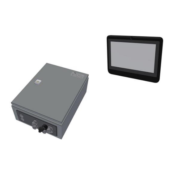
3. TECHNICAL SPECIFICATIONS Drawing 0815-1130 (section 17) SDB-3 Supply voltage 115 - 230 VAC Power consumption 24 W max. Ingress Protection IP44 Net weight Approx. 8 kg Operating temperature °C -20 to 55 Dimensions 400 x 300 x 155 mm (w x h x d) 1GHz, SDRAM 512MB DDR3L 800 MHZ, On board flash 2GB, 8bit embedded MMC... - Page 7 Figure 1 SDB-3 ShaPoLi Data Box Drawing 0815-1128 (section 17) Bridge Panel PC Supply voltage 115-230 VAC to power supply unit Dimensions 218 x 163 x 47 mm (w x h x d) Cut out 170 x 120 mm (w x h) Cut out depth 32 mm Front panel thickness...
-
Page 8: Safety Instructions
4. SAFETY INSTRUCTIONS There are no special safety instructions for the equipment. 5. UNPACKING Let the equipment acclimatize inside the closed box for at least one hour at the location where the system will be installed. When the equipment is taken out of the box, please leave the special protection supplied with the equipment if possible in place to avoid any damage. -
Page 9: Installation Diagram
6.2 INSTALLATION DIAGRAM Below the configuration where two T-/TT-sense sensors are connected to the SDB-3. The Bridge Panel PC is connected to the SDB-3 via the Ethernet cable as shown in below figure. Figure 3 – Installation diagram SDB3 to the Bridge Panel PC with two T-/TT-Sense 6.3 INSTALLATION INSTRUCTION OF THE SDB-3 AND BRIDGE PANEL PC SYSTEM ®... - Page 10 Always install the SDB-3 with cable glands facing downwards. Do not take electronics out of the cabinet. Figure 5 – SDB-3 positioning 2. Install the SDB-3 in the engine room (ER) or engine control room (ECR) but as much as possible free from moisture, free from large fluctuations of temperature and particularly free from vibration and shock.
- Page 11 Important notes • Never connect cable shields at both ends to ground, but at one end only, to avoid earth loops. • Avoid interference on the signal cables by installing them as far as possible away from electric power cables. •...
-
Page 12: Configuration And Connection Of The Sdb-3
6.4 CONFIGURATION AND CONNECTION OF THE SDB-3 Processor module Backplane with analogue input modules (Optional) 24 VDC Power supply DIN-rail connectors power & Earthing External earth on gland-plate Figure 6 – SDB-3 Cabinet lay-out 6.4.1 Earthing of the SDB-3 enclosure The SDB-3 enclosure must be earthed externally. -
Page 13: Halogen Free
6.5.2 Halogen free In areas where equipment sensitive to corrosion is installed or kept, use of Halogen free cables should be considered to avoid corrosive smoke in case of a fire, as far as is practicable. This is according to IEC 60754-1. -
Page 14: Modbus Input For T-Sense And Tt-Sense
The T-Sense or TT-Sense stator control box slave address is factory set by VAF Instruments. The SDB-3 termination resistor can be set by way of a jumper switch in “on”-position. The termination resistor of the last device depends on the device. This can be done using a resistor or... -
Page 15: Rd Party Torque Meter
Terminal nr. X3 and X4 Shaft power signal 4–20mA - active Terminal nr. X5 and X6 When passive analogue outputs must be connected to the SDB-3 please contact VAF Instruments. NOTE: Do not connect the signal ground to the ship hull. NOTE:... -
Page 16: Operating Principles
7. OPERATING PRINCIPLES 7.1 GENERAL A zero-setting procedure is always necessary in order to obtain a correct measurement and reading of ® ® the T-Sense Torque sensor or TT-Sense Thrust & Torque sensor. ® ® For more detailed information see section 6.4 of TIB-661 T-Sense or TIB-664 TT-Sense The SDB-3 and Bridge Panel PC is an integrated solution for monitoring shaft power and triggers audible and visible alarm when the EEXI power limit is exceeded. -
Page 17: Speed Over Ground (Sog) Via Nmea 0183
7.3.4 Speed Over Ground (SOG) via NMEA 0183 A GPS signal can be connected to the SDB-3 through the RS422 port (J4). The ship’s speed over ground is transmitted via the NMEA 0183 protocol. The SDB-3 and Bridge Panel PC will read out the $--RMC sentence (“Speed Over Ground”) and the value will be displayed in knots. The ship’s through water is transmitted via the NMEA 0183 protocol. -
Page 18: How To Operate
7.4 HOW TO OPERATE The VAF Bridge Panel PC is designed in such a way that it is easy to operate and self-explaining. By touching the keys on the touch screen gently the next menu is selected, or specific values can be changed. -
Page 19: Explanation Of The Menus
7.5 EXPLANATION OF THE MENUS The Bridge Panel PC is divided into 5 submenu’s: ShaPoLi, Event Logs, Alarms, Signals and Settings. By touching the relevant tab, the specific menu will be displayed. 7.5.1 ShaPoLi Home screen By touching the ShaPoLi tab in the top left corner you will be guided to the ShaPoLi home screen. The ShaPoLi home screen is showing all important actual information regarding Shaft Power Limitation. - Page 20 Figure 13 – ShaPoLi home screen when Shaft power is Figure 14 – ShaPoLi home screen when communication with above EEXI limit Power sensor is lost – Figure 16 – ShaPoLi home screen when one of the expected Figure ShaPoLi home screen when...
-
Page 21: Event Logs
7.5.2 Event Logs In the submenu Event Logs all the Logging events are listed. For example, when the Actual shaft Power is exceeding the EEXI Power limit, the event will be listed in this Event log menu. The user can Verify an event by touching the Verify event button. In this submenu the Start time and End time will be shown. -
Page 22: Alarms
Besides the Power limitation event there are five more events that are logged in the Event Log menu: Event type: Causes: Verification needed: Power above limit Shaft power exceeds the EEXI power limit SDB-3 was turned off The power of the SDB-3 was turned off The settings-file with EEXI limit is missing Missing settings One of the two power-sensors have not... - Page 23 If an alarm is triggered, the following happens: The green bar in the ShaPoLi home screen will change to red The ShaPoLi tab and Alarms tab will change to red and blinks The normally closed Digital Output is opened The speaker of the VAF Bridge Panel PC beeps for half a second, every second The SDB-3 software starts logging Alarm Log: All alarms will be logged in the Alarm log submenu.
- Page 24 The following alarms might appear: Alarm description Possible cause Power above limit The actual shaft Power is over the EEXI Shaft Power Limit Tsense 1 or 2 CommFail Modbus connection/cable between SDB-3 and T-/TT-sense stator control box is broken or wrongly connected. Remark: First try to swap the 2 Modbus signal wires.
-
Page 25: Signals
NOTE: Alarms can only be silenced / accepted via the VAF Bridge Panel PC! 7.5.4 Signals Within the Signals menu you can monitor the raw signals coming in from the different sensors, connected to the SDB-3: → Torque, Speed and Power from T-Sense ®... -
Page 26: Settings
7.5.5 Settings By entering the password (1234) and touching the Log in button the Settings menu is opened. In this menu you can choose to show the orange zone of the ShaPoLi gauge in the ShaPoLi Home screen. This orange zone represents the Power area between the green and red zone on the ShaPoLi gauge. -
Page 27: Malfunction And Send For Repair
12. MALFUNCTION AND SEND FOR REPAIR If the SDB-3 and Bridge Panel PC stops working completely contact VAF Instruments for instructions. In the event the SDB-3 and Bridge Panel PC parts has to be sent back for repair, you can send it directly VAF Instruments B.V. -
Page 28: Drawings
17. DRAWINGS DWG# DWG NAME 0815-1236 Part list ShaPoLi data box SDB-3 0815-1130 Dimensional Drawing SDB-3 0815-1128 Dimensional Drawing Bridge Panel PC 0815-2059 Connection Drawing Bridge Panel PC 0815-2054 Sheet 1 of 2 Connection diagram ShaPoLi SDB-3 & Bridge Panel PC 0815-2054 Sheet 2 of 2 Connection diagram ShaPoLi SDB-3 &... - Page 29 Drawing 0815-1130 Dimensional drawing ShaPoLi Data Box SDB-3 Drawing 0815-1128 Dimensional Drawing / Connections Bridge Panel PC...
- Page 30 Drawing 0815-2059 Connection Drawing Bridge Panel PC Drawing 0815-2054 Sheet 1 of 2 Connection diagram SDB-3 & Bridge Panel PC...
- Page 31 Drawing 0815-2054 Sheet 2 of 2 Connection diagram SDB-3 & Bridge Panel PC Drawing 0815-2055 Schematic diagram ShaPoLi...
- Page 32 Drawing 0815-1127 SDB-3 installation position...
- Page 33 Example of a Shaft power limitation event report...
-
Page 34: Abbreviations
18. ABBREVIATIONS Alarm and Monitoring System Central Processing Unit Engine Control Room Engine Room EEXI Energy Efficiency Existing ship Index Liquid Crystal Display NMEA 0183 National Marine Electronics Association protocol 0183 for serial data transfer RS485 Serial interface for long distance data communication SDB-3 ShaPoLi Data Box Thin Film Transistor - Liquid Crystal Display... -
Page 35: Warranty Conditions
20. WARRANTY CONDITIONS 1. Without prejudice to the restrictions stated hereinafter, the contractor guarantees both the soundness of the product delivered by him and the quality of the material used and/or delivered for it, insofar as this concerns faults in the product delivered which do not become apparent during inspection or transfer test, which the principal shall demonstrate to have arisen within 12 months from delivery in accordance with sub article 1A exclusively or predominantly as a direct consequence of unsoundness of the construction used by the contractor or as a consequence of faulty finishing or the use of poor... - Page 36 4. Defects not covered by the guarantee are those which occur partially or wholly as a result of: A. non-observance of the operation and maintenance instructions or other than foreseeable normal usage; B. normal wear and tear; C. assembly/installation by third parties, including the principal; D.
Need help?
Do you have a question about the Shapoli 620 and is the answer not in the manual?
Questions and answers