Table of Contents
Advertisement
Available languages
Available languages
Quick Links
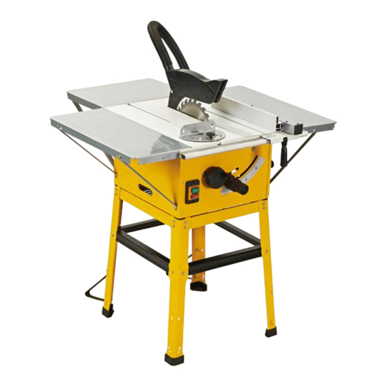
Pilarka stołowa
table saw
Instrukcja obsługi / Manual
NUMER MODELU / INDEX:
SM-04-02050
oryGINaLNa INstruKCJa oBsŁuGI / orIGINaL MaNuaL
Dla własNeGo beZPieCZeŃstwa
PrZeCZYtaJ Ze ZroZUMieNieM CałĄ iNstrUkCJĘ PrZeD roZPoCZĘCieM
UŻYtkowaNia aGreGatU.
For your saFety
read and understand the entire manual before operating machine
Advertisement
Table of Contents

Summary of Contents for SMART SM-04-02050
- Page 1 Pilarka stołowa table saw Instrukcja obsługi / Manual NUMER MODELU / INDEX: SM-04-02050 oryGINaLNa INstruKCJa oBsŁuGI / orIGINaL MaNuaL Dla własNeGo beZPieCZeŃstwa PrZeCZYtaJ Ze ZroZUMieNieM CałĄ iNstrUkCJĘ PrZeD roZPoCZĘCieM UŻYtkowaNia aGreGatU. For your saFety read and understand the entire manual before operating machine...
- Page 2 Należy zwrócić szcze- Zabrania się demontażu urządzeń ochronnych gólną uwagę na uwagi i ostrzeżenia. i zabezpieczających oraz manipulowania przy nich. 2. DaNe teCHNiCZNe sM-04-02050 Indeks Uwaga! Ryzyko obrażeń! Parametry techniczne Zbliżanie rąk do tarczy 2000 W tnącej grozi poważnymi Wymiary piły...
- Page 3 5. oGólNe ZasaDY beZPieCZeŃstwa • Chronić oczy, twarz i głowę przed przedmiotami, które mogą zostać wyrzucone z urządzenia. Podczas Użytkowanie maszyny pracy należy zawsze nosić gogle ochronne lub oku- • Należy zapoznać się z niniejszą instrukcją obsługi lary ochronne z osłonami bocznymi. oraz etykietami umieszczonymi na urządzeniu, aby • Należy nosić...
- Page 4 6. sZCZeGółowe ZasaDY Bezpieczeństwo elektryczne • Należy zabezpieczyć się przed porażeniem prą- beZPieCZeŃstwa dem elektrycznym. Nie wolno podłączać ani odłą- Środki ostrożności czać silnika, stojąc na lub w pobliżu wilgotnego lub • Nie używać zużytych, pękniętych lub zdeformowa- mokrego podłoża. Nie należy używać urządzenia nych tarcz tnących.
- Page 5 i ogranicznika, aby zapobiec jego odbiciu i wykrę- drewna, należy wyłączyć urządzenie. ceniu. • Prace nastawcze i pomiarowe oraz czyszczenie • Jeśli podczas cięcia tarcza zablokuje się z powodu urządzenia należy wykonywać tylko przy wyłączo- zastosowania nieprawidłowej siły posuwu, należy nym silniku.
- Page 6 rękawice ochronne. ich bezawaryjności i prawidłowego funkcjonowa- • Przed użyciem narzędzi tnących należy upewnić nia. Sprawdzić, czy części ruchome działają bez zarzutu i nie zakleszczają się lub czy nie są uszko- się, że wszystkie urządzenia ochronne są prawi- dzone. Aby zapewnić bezawaryjną pracę elektro- dłowo zamocowane.
- Page 7 CONTENTS SUPPLIED CONTENTS SUPPLIED The table saw comes partially assembled and is shipped in carefully packed carton. After all the 7. ZawartoŚĆ ZestawU parts have been removed from the carton, you should have: Piła stołowa jest częściowo zmontowana i dostarczana w starannie zapakowanym kartonie. Po wyjęciu z kartonu The table saw comes partially assembled and is shipped in carefully packed carton.
- Page 8 8. MoNtaŻ Niniejsza stołowa pilarka tarczowa została wstępnie zmontowana w fabryce. W celu dokończenia montażu należy postępować zgodnie z poniższymi wskazów- kami. Przedłużenia stołu 1. Obrócić urządzenie do góry nogami i położyć je na podłodze. 2. Wyrównać przedłużenia względem stołu. 3.
- Page 9 tów w lewą stronę. Patrz rysunek 3. Korbka regulacji wysokości 4. Włożyć klin rozszczepiający za płytę zaciskową i wci- 1. Odwrócić piłę i upewnić się, że stoi na płaskim pod- łożu. snąć do samego końca w dół. 5. Delikatnie dokręcić śrubę zaciskową ruchem 2.
- Page 10 ścić na klinie rozszczepiającym. Śruba motylkowa Prowadnica kątowa 1. Wprowadzić prowadnicę kątową w rowek w stole, wejdzie w rowek w kształcie litery L w klinie rozsz- czepiającym, a następnie należy odciągnąć osłonę rozpoczynając od jego przedniej krawędzi. 2. Po poluzowaniu pokrętła prowadnicy kątowej należy tarczy do tyłu, by śruba motylkowa idealnie wpaso- wała się...
- Page 11 9. iDeNtYfikaCJa PoDZesPołów 1. Osłona tarczy 9. Klin rozszczepiający 2. Przedłużenie stołu 10. Tarcza tnąca 3. Stół 11. Prowadnica równoległa 4. Prowadnica kątowa 12. Dźwignia blokująca 5. Blokada pochylenia tarczy 13. Wskaźnik kąta pochylenia 6. Pokrętło pochylenia tarczy 14. Popychacz 7.
- Page 12 Przełącznik oN/off Jeśli wskaźnik pochylenia nie znajduje się na pozycji Piłę uruchamia się poprzez naciśnięcie zielonego przy- zerowej, gdy kąt pomiędzy tarczą a stołem wynosi 90°, cisku. W celu wyłączenia piły należy nacisnąć czerwony należy wyregulować wskaźnik poprzez poluzowanie przycisk. śruby i ustawienie 0°...
- Page 13 • Prowadnicę można zamontować po obu stronach przedniej krawędzi osłony tarczy. 5. Zawsze należy przeprowadzać obrabiany przedmiot stołu. • Przy pomocy podziałki na szynie prowadzącej aż do końca klina rozszczepiającego. 6. Odcięty fragment pozostaje na tarczy piły aż do jej można ustawić...
- Page 14 12. traNsPort przedmiotem w stronę tarczy w celu wykonania cięcia. Uwaga! Należy zawsze trzymać prowadzoną część 1. Przed transportem należy wyłączyć elektronarzędzie obrabianego przedmiotu. Nigdy nie trzymać czę- i odłączyć je od sieci zasilającej. ści, która ma zostać odcięta. 2. Elektronarzędzie należy przenosić w co najmniej 5.
- Page 15 z klina rozszczepiającego. Delikatnie wyjąć osłonę zewnętrzny kołnierz tarczy. Patrz rysunek 6 poniżej. 13. Następnie zdjąć tarczę z wału napędowego i ostroż- tarczy. Patrz rysunek 1 poniżej. 5. Poluzować dwie śruby mocujące i wyjąć wkładkę nie wyciągnąć ją ze stołu pilarki. Patrz rysunek 6 stołu.
- Page 16 Problem Przyczyna Rozwiązanie • Założyć naostrzoną tarczę Brak mocy/ 1. Przeciążenie spowodowane • Silnik można uruchomić silnik wyłącza się automatycznie stępioną tarczą tnącą 2. Aktywowane zabezpieczenie ponownie po jego ostygnięciu. termiczne • Wymienić tarczę Nadmierne drgania 1. Niewyważona tarcza • Wymienić tarczę 2.
- Page 17 PARTS SCHEDULE TABLE SAW...
- Page 18 oPis iloŚĆ oPis iloŚĆ Gumowa stopka Śruba M8x16 Podpórka Podkładka sprężynująca 8 Podkładka 6 Uchwyt wałka Podkładka sprężynująca 6 Płytka mocująca wałka Śruba 8.8 M6x16 Wspornik I Śruba 8.8 M6x12 Śruba (Zn) M5x14 Nakrętka kołnierzowa M6 Nakrętka zabezpieczająca M5 Śruba M4x16 Śruba M5x25 Śruba M5x12 Łożysko igiełkowe typu drawn-cup...
- Page 19 oPis iloŚĆ oPis iloŚĆ 147. Prawa płyta boczna Popychacz 148. Przedłużenie stołu Obudowa 100. Prowadnica 149. Podkładka 5 101. 150. Śruba M6x45 Gumowa stopka 102. Czworokątna rurka 151. Wspornik wzdłużny 103. 152. Zaślepka czworokątnej rurki Noga 104. Długa podkładka dystansowa 153.
-
Page 20: Table Of Contents
50% at 40°C. It and maintenance of the can be storedor transported under ambient tempera- splitter! tures between -25°C and 55°C. Keep children and bystanders sM-04-02050 Index off and away. specifications Power 2000 W Blade dimensions 250 / 30 mm T24 4. - Page 21 proper operation. Know how to stop the machine pery surfaces. Keep proper footing and balance at all and disengage the controls quickly. times. This enables better control of the machine in • Do not attempt to operate the machine until you unexpected situations.
-
Page 22: Specific Safety Rules
in a damp or wet environment. Make sure that the feed force during cutting, turn the machine off and work area is well-illuminated. Do not use electric disconnect it from power supply. Remove the work tools where there is a risk of fire or explosion. piece and ensure that the saw blade runs free. - Page 23 sive medical implants under certain conditions. In with the use of a suitable extraction system. order to prevent the risk of serious or deadly injuries, Maintenance and Repair we recommend that persons with medical implants • Pull out the mains plug for any adjustment or repair consult with their physician and the manufacturer tasks.
-
Page 24: Contents Supplied
CONTENTS SUPPLIED CONTENTS SUPPLIED The table saw comes partially assembled and is shipped in carefully packed carton. After all the 7. CoNteNts sUPPlieD parts have been removed from the carton, you should have: The table saw comes partially assembled and is shipped in carefully packed carton. After all the parts have been The table saw comes partially assembled and is shipped in carefully packed carton. -
Page 25: Assembly
the support struts onto the main frame with This table saw was partially assembled at the Support Legs Bench Extensions the bolts M6×16, spring washers and flat factory. To assemble your machine follow the washers. 1. Screw the four support legs together with 1. - Page 26 2. Unscrew the bevel limitation stopper, turn M6 × 12 × 20 the bevel adjusting handwheel to set the blade to the 0 position and fasten the bevel limitation stopper. See below illustration 2. Height Adjusting Handlebar Height Adjusting Handlebar 1.
- Page 27 8. Fasten the bench insert into the saw table with both Miter Gauge 1. Insert the miter gauge into the table slot from the fixing screws. See illustration 6. 9. Insert the batteries. table’s front edge. 2. Set the desired angle after loosening the miter gau- Saw Blade Guard &...
-
Page 28: Know Your Machine
9. kNow YoUr MaCHiNe 1. Saw Blade Guard 9. Riving Knife 2. Bench Extension 10. Blade 3. Saw Bench 11. Rip Fence 4. Miter Guage 12. Locking Lever 5. Bevel Limitation Stopper 13. Bevel Indicator 6. Bevel Adjusting Wheel 14. Push Stick 7. -
Page 29: Set Up
oN/off switch screw. The saw can be switched on by pressing the green Unplug the saw. pushbutton. The red pushbutton has to be pressed to Loosen the bevel limitation stopper. switch off the saw. Set the desired angle on the scale by pressing and turn- ing the bevel adjusting handwheel. -
Page 30: Operation
cut, never adopt a working position that is in Low stop rail: thin material There are two miter gauge channels, one on Making Longitudinal Cuts line with the cutting direction. Set the rip fence to the desired level in the either side of the blade. -
Page 31: Transport
Making Cross Cuts • Immediately switch the table saw off and pull the 1. Slide the miter gauge into one of the grooves in the mains plug out of the socket if the saw blade catches table and adjust to the required angle. If you want in the workpiece or any other blockages occur. -
Page 32: Storage
direc the crank counterclockwise up to the stop 11. Turn the fixing nut in an anti-clockwise the s point. direction using the ring spanner. 4. Remove the saw blade guard from the 12. Carefully hold the saw blade with one hand 16. -
Page 33: Trouble Shooting
15. troUble sHootiNG Problem Cause Remedy • Check the mains fuse Motor does not start 1. Fastening nut tightened insuf- ficiently • Check the extension cable • Have it checked by an 2. Extension cable defect electrician 3. Connections on the motor or switch defect • Insert a sharpened saw blade No Motor output turns off... - Page 34 PARTS SCHEDULE TABLE SAW...
- Page 35 oPis iloŚĆ oPis iloŚĆ Rubber Foot Screw M8x16 Support Strut Spring Washer 8 Washer 6 Shaft Holder Spring Washer 6 Shaft Fixing Plate Bolt 8.8 M6x16 Support Bracket I Bolt 8.8 M6x12 Screw (Zn) M5x14 Flange Nut M6 Lock Nut M5 Screw M4x16 Screw M5x25 Screw M5x12...
- Page 36 oPis iloŚĆ oPis iloŚĆ 148. Table Length Extension Housing 100. 149. Rip Fence Washer 5 101. Bolt M6x45 150. Rubber Foot 102. 151. Square Tube Longitudinal Strut 103. End Cap For Square Tube 152. 104. 153. Long Spacer Cross Strut 105.
- Page 37 2019...
- Page 39 warUNki GwaraNCJi warraNtY Firma ERPATECH udziela gwarancji na sprawne działa- Provides a warranty for correct operation of the tool. nie urządzenia. The warranty period begins from the date of handing Niniejszą gwarancją objęte są wady produkcyjne urzą- over to the user and lasts 12 months, while the consu- dzenia uniemożliwiające jego użytkowanie zgodnie mer warranty (purchase with receipt) lasts 24 months.
- Page 40 ErpatEch ul. Bakaliowa 26 05-080 Mościska tel. 22 – 431 05 05 „Erpatech” ul. Bakaliowa 26 05-080 Mościska tel. 22 – 431 05 05 KARTA GWARANCYJNA Nazwa produktu …………………………………………………. Numer seryjny ……………………………………………………. Data sprzedaży …………………………………………………… ……………………………………. Faktura / Paragon ………………………………………………. pieczątka i podpis sprzedawcy Oświadczenie Nabywcy.
Need help?
Do you have a question about the SM-04-02050 and is the answer not in the manual?
Questions and answers