Table of Contents
Advertisement
Quick Links
Advertisement
Table of Contents

Summary of Contents for Thales KPG-opt 4FSM-IN
- Page 1 Optical Multi Meter KPG-opt 4FSM-IN General Product Information KPG-opt 4FSM...
-
Page 3: Table Of Contents
KPG-opt Table of content Introduction Purpose Description Material Technical Data Electrical Data Mechanical and climatic data Front View Design Operation Main Functions Operations construction team 5.1.1 Cable drum test 5.1.2 Measurement of a deployed cable Measurements Diagnosticians 5.2.1 Power meter 5.2.2 Testframe 5.2.3... -
Page 4: Introduction
KPG-opt Introduction Purpose 1 The Optical Multi Meter KPG-opt is designed to test fiber optic cable drums and entire fiber optic links. 2 The KPG-opt supports diagnosticians to detect possible failures in the fiber optic link. Description The following main measurements are foreseen: 3 Construction teams: - Attenuation measurement of an optical cable drum with 2 or 4 fibers, single mode. - Page 5 KPG-opt - Optical power source with selectable power level - Optional transmission of user specific data frames...
-
Page 6: Material
KPG-opt Material Figure 1 – KPG-opt Material Description KPG-opt Batteries (AA-Type, LR6) -
Page 7: Technical Data
KPG-opt Technical Data Electrical Data 7 Transmitter (Single Mode) 1310 nm ± 40 nm Tx Power Level for cable – 5 dBm test – 3 ... – 12 dBm Tx Level for optical power source Stability of Tx Level ± 1 dBm Rx measurement range –... -
Page 8: Mechanical And Climatic Data
KPG-opt 3.2 Mechanical and climatic data 8 Dimensions L x B x H Equipment 270 x 145 x 80 mm Weight Equipment 1.6 kg Temperature Operation – 10 to + 50 °C Storage – 30 to + 60 °C Humidity IP 64... -
Page 9: Front View
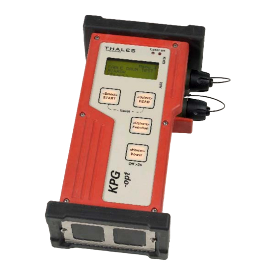
KPG-opt Outline Front View Laser on Reset Off >2sec Figure 2 – KPG-opt front view... - Page 10 KPG-opt Description LCD – Display Sensor (Brightness control for display) LED Laser on optical Connector "MAIN" with protection cap optical Connector "AUX" with protection cap Keypad Rubber bumper (Shock absorber)
- Page 11 KPG-opt Figure 3 – KPG-opt Back view Description Connector external power supply 10-36 Battery cover Quick lock for battery cover...
-
Page 12: Design
KPG-opt Design 13 The KPG-opt is built in an shock resistant plastic housing with a ruggedized keypad with four keys. 14 An LCD display with four lines shows the functions and the results of the measurements. The menu guidance simplify the operations. 15 Two optical connectors are mounted at the side to enable easy connection of the fiber optical cable. -
Page 13: Operation
KPG-opt Operation 17 The KPG-opt is operated with four keys. The available menus are shown in the display and the required functions can be easily selected with the menu keys. The results of the measurements are shown in the display and some tests are rated with a good/bad indication. -
Page 14: Main Functions
KPG-opt Main Functions Operations construction team 5.1.1 Cable drum test Laser on <Select> <Select> START READ Reset <Return> Function <Home> Power off>2sec Figure 4 – Drum test 20 Attenuation measurement of a cable drum in dB using the „CABLEDRUM“ - test. To test 4 fibers, a loop connector is required. -
Page 15: Measurement Of A Deployed Cable
KPG-opt 5.1.2 Measurement of a deployed cable KPG-opt LOCAL Loop connector Figure 5 – Cable test... - Page 16 KPG-opt 22 Test of a fiber optical cable before, during and after field deployment. Attenuation: Attenuation of the entire link in dB.
-
Page 17: Measurements Diagnosticians
KPG-opt Measurements Diagnosti- cians Laser on <Select> <Select> START READ Reset <Return> Function <Home> Power off>2sec Figure 6 - KPG-opt with optical interface cable Measurements and diagnostics on the equipment: - Power meter function - Optical source (unmodulated) -
Page 18: Power Meter
KPG-opt 5.2.1 Power meter The KPG-opt measures the optical power which is received through the optical cable. The Receiver is calibrated between a range of −35 dBm to 0 dBm to measure optical power at the main connector. An optional attenuator cable can be used to lower the signal. -
Page 19: Testframe
KPG-opt 5.2.2 Test frame (option) The KPG-opt can be optionally prepared to generate „Test Frames“ which can be detected by the equipment in the system. This feature can be used for diagnostics and function checks. The output power can be adjusted with the <Select> key within the range of −5 to −15 dBm in 1 dB Steps. -
Page 20: Optical Source
KPG-opt 5.2.3 Optical Source KPG-opt used as optical source (Laser transmitter). A continuous optical signal is generated and sent to the main connector with constant power. The output power can be adjusted with the <Select> key within the range of –3 to –12dBm in 1 dB Steps. An optional attenuator cable (PK-opt -18 dB) can be used to lower the signal by 18dB. -
Page 21: Safety Regulations
KPG-opt Safety regulations Operator protection safety regulations within customer organizations have to be followed. Obey the grounding regulations and all electrical rules. Prior to opening the battery compartment the KPG- opt has to be separated from the optical cable. INVISIBLE LASER RADIATION. THE LOW POWER SYSTEM IS EYESAFE. - Page 22 KPG-opt The predetermined procedures for activities have to be followed. Equipments and accessories shall be transported in the foreseen compartments. The protection caps have to be in place for transportation.
Need help?
Do you have a question about the KPG-opt 4FSM-IN and is the answer not in the manual?
Questions and answers