
Subscribe to Our Youtube Channel
Related Manuals for STIL CHR 150

Summary of Contents for STIL CHR 150
- Page 1 sales@artisantg.com artisantg.com (217) 352-9330 | Visit our website - Click HERE...
- Page 2 CHR 150 Operating and maintenance manual STIL S.A. 595, rue Pierre Berthier – Domaine de Saint Hilaire – 13855 Aix-en-Provence cedex 3, France Tel: +33 (0)4 42 39 66 51 – Fax : +33 (0)4 42 24 38 05 Email : stil.sa@wanadoo.fr...
-
Page 3: Table Of Contents
STIL - CHR 150 – Operating and maintenance manual Doc ref. CHR2-001-P2 Rev :D CONTENTS PRESENTATION OF THE RANGE OF CHR SENSORS ..............4 PRESENTATION OF THE CHR 150 ......................4 ............................4 ONTROLLER ......................5 PTICAL PEN AND OPTICAL FIBER SAFETY ................................. - Page 4 STIL - CHR 150 – Operating and maintenance manual Doc ref. CHR2-001-P2 Rev :D ..........35 IMITATION OF THE AMOUNT OF DATA TRANSMISSIBLE SIMULTANEOUSLY ........................36 ECODING OF THE DATA ADVANCED FUNCTIONS ........................37 10.1 ........................37 ETECTION HRESHOLD 10.2 «...
-
Page 5: Presentation Of The Range Of Chr Sensors
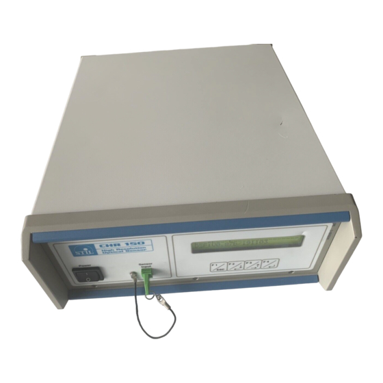
For further information on the optical measurement principle which forms the basis of the STIL technology, and for an overview of available products, visit the STIL company web site at the following address: www.stilsa.com Presentation of the CHR 150 The CHR 150 consists of an opto-electronic unit (“controller”) and one or more interchangeable... -
Page 6: Optical Pen And Optical Fiber
STIL - CHR 150 – Operating and maintenance manual Doc ref. CHR2-001-P2 Rev :D The rear panel of the controller features: Optional optical fiber Socket for connecting optical pen 2 Analog output coaxial sockets Sync in & Sync Coaxial sockets... -
Page 7: Safety
STIL - CHR 150 – Operating and maintenance manual Doc ref. CHR2-001-P2 Rev :D Safety The CHR 150 is an opto-electronic instrument. It is safe in normal operating conditions: Thermal Hazards The temperature of the Halogen lamp and its support is very high. -
Page 8: Installation And Switching On
STIL - CHR 150 – Operating and maintenance manual Doc ref. CHR2-001-P2 Rev :D Installation and switching on Connect the controller to a mains socket with an earth connection, then connect the optical fiber lead from the optical pen to the controller, taking care to comply with the correct orientation of the connector. -
Page 9: Communicating With The Chr 150
Doc ref. CHR2-001-P2 Rev :D Communicating with the CHR 150 There exist 5 alternative methods for communicating with the CHR 150 sensor: a) The CHR front panel displays real time measurements and the 4-keys keypad allows a direct and easy access to sensor configuration. -
Page 10: Getting Started (Tutorial 1)
This chapter is a tutorial intended for new users who wish to familiarise themselves with the main characteristics of the CHR 150 sensor. For simplification purposes, this tutorial only introduces one measuring mode (« Distance » mode) and one communication method (the control panel). We recommend that new users follow this tutorial even if they wish subsequently to use another measuring mode or a different method for communicating with the sensor. - Page 11 STIL - CHR 150 – Operating and maintenance manual Doc ref. CHR2-001-P2 Rev :D Main menu MAIN ONFIG LEAR • To access the Main menu of the Control panel, press any key. • The S.Rate and the configuration menus are both described below.
- Page 12 STIL - CHR 150 – Operating and maintenance manual Doc ref. CHR2-001-P2 Rev :D Configuration Menu ONFIG Select Serial data Config. Data Take white detect. ASCII/BIN Analog measuring averaging Contrast reference threshold out1 mode Select serial Config. Spectral Set default...
-
Page 13: Selecting The Optical Pen
The CHR-150 controller may hold up to 6 calibration tables corresponding to 6 different optical pens. Available optical pens and their characteristics may be consulted in STIL website : www.wtilsa.com. Optical pens are passive devices and the controller can not identify the optical pen which is physically connected to it, so the operator has to select the calibration table corresponding to the optical pen that is physically connected. -
Page 14: Positioning The Sample Within The Measurement Range Of The Optical Pen
STIL - CHR 150 – Operating and maintenance manual Doc ref. CHR2-001-P2 Rev :D Clean the ends of the optical fiber as described in the maintenance section of this manual, then repeat the dark signal acquisition and check that the warning message does not reappear. -
Page 15: Understanding The Meaning Of The Intensity Measurement
STIL - CHR 150 – Operating and maintenance manual Doc ref. CHR2-001-P2 Rev :D Understanding the meaning of the intensity measurement The « Intensity » parameter measured by the sensor is an indication of the brightness of the signal reflected back off the sample, as a percentage of the dynamic response of the sensor. Its value is dependent on several parameters: •... -
Page 16: Going Further (Tutorial 2)
Synchronisation signals (« Trigger » ). Measuring modes The main measuring mode for the CHR 150 sensor is “Distance” mode . The sensor is calibrated and tested by the manufacturer in this measuring mode, and a certificate of the test results is supplied with each optical pen. -
Page 17: Configuring The Sensor In "Thickness" Measuring Mode
STIL - CHR 150 – Operating and maintenance manual Doc ref. CHR2-001-P2 Rev :D Configuring the sensor in “Thickness” measuring mode In this measuring mode the sensor searches for 2 signals, reflected from the 2 faces of the sample. If they are found, it calculates the intensity and Distance of face 1 (front face, i.e. -
Page 18: Configuring The Sensor In " Interferometric " Measuring Mode
STIL - CHR 150 – Operating and maintenance manual Doc ref. CHR2-001-P2 Rev :D Configuring the sensor in « Interferometric » measuring mode The “Interferometric” measuring mode is optional. If your sensor is not equipped with this option, skip to the next section (§7.4). -
Page 19: Configuring The Sensor In " Min/Max " Measuring Mode
STIL - CHR 150 – Operating and maintenance manual Doc ref. CHR2-001-P2 Rev :D Example : starting from non-bracketed mode bracketed mode, LH edge selected displacement of the LH edge to the left displacement of the LH edge to the right... - Page 20 STIL - CHR 150 – Operating and maintenance manual Doc ref. CHR2-001-P2 Rev :D The diagram below shows an example of the operating sequence : « Activate Inspection Inspection inspection » inspection activated inspection activated inspection signal Max threshold Thickness...
-
Page 21: Communicating With The Chr 150 Via The Rs232 Link
COM2) using a direct (non crossed) serial link wire. • From the CHR 150 control panel enter the Configuration menu and verify that the baud rate is set at 115200 baud. Set transmission format (‘serial data’ menu) at ASCII and the data averaging at 99 to reduce the data transmission rate. -
Page 22: Using The "Trigger" Mode
The « Sync in » signal is used to synchronise the CHR 150 sensor with external events, such as the approach of an object travelling on a conveyor belt. This mode must be activated by a special command (cf. -
Page 23: Main Functions Of The Chr 150
The ‘Dark’ command records and saves of the dark signal in the EEPROM of the CHR 150 for all sampling rates in succession. If the level of the dark signal is too high for low rates, the CHR 150 returns the index of the lowest sampling rate which is usable (see ‘Set Sampling rate’ command). -
Page 24: Sampling Rate Selection
STIL - CHR 150 – Operating and maintenance manual Doc ref. CHR2-001-P2 Rev :D 8.2.2 Fast Dark The « Fast Dark » function only refreshes the dark signal for the current acquisition frequency, without saving the recording in the EEPROM. If the dark signal measured is too high, the CHR150 returns a «... - Page 25 STIL - CHR 150 – Operating and maintenance manual Doc ref. CHR2-001-P2 Rev :D 8.3.2 Set/request the free sampling rate (‘ Free Rate’ ) The ‘Free Rate’ function is used to Set/request the value in Hz attributed to the free sampling rate.
-
Page 26: Measuring Mode Selection
PC acquisition board for example). Synchronisation is achieved using the "Sync out" output on the CHR 150 (TTL clock signal at the sensor sampling rate). The analog values must be latched to the rising front of the Sync out signal... -
Page 27: Averaging
The CHR 150 provides two types of time-domain averaging : data averaging and spectral averaging. In the first type, the averaging is performed on the measured data (after processing), in the second type, it is performed on the spectrometer signal (before processing). -
Page 28: Synchronisation Signals
The « Start Trigger » function puts the sensor on standby for a Trigger signal at the “Sync in” input (pin 1) on the SUB-D connector (cf. « Presentation of the CHR 150 »). The sensor activates as soon as a rising front is detected at the “Sync in”... -
Page 29: Request/Save The Current Configuration
STIL - CHR 150 – Operating and maintenance manual Doc ref. CHR2-001-P2 Rev :D 8.8.2 One-point trigger standby (« One-point Trigger ») The « One-point Trigger » function is similar to the “Start trigger” function, with the following difference: when the “Sync in” signal is received, the sensor transmits the data of a single measured point and stops immediately. -
Page 30: Read The Version Of The On-Board Software
EEPROM. This is essential for the sensor to be able to retrieve the configuration when it is next switched on. If this is not done, the next time the CHR 150 is switched-on the sensor will lose all the latest modifications made. -
Page 31: Lock Or Unlock Access To Keypad
8.11 Lock or unlock access to keypad This command activates or deactivates the keyboard. Locking the keyboard can be very useful when handling the CHR 150 with a machine. Warning: after switching the CHR OFF and ON again, the keypad is automatically activated... -
Page 32: Control And Acquisition Of The Data Via The Serial Link
Doc ref. CHR2-001-P2 Rev :D Control and acquisition of the data via the serial link The CHR 150 incorporates an RS232 serial link for controlling the sensor using a specific control language, and for retrieving the measurement data. The RS232 sub D at the CHR-150 controller back panel should be connected to a free COM Port on the host computer (COM1 or COM2) or on the device used for communicating with the sensor, using a direct (non-crossed) serial link wire. -
Page 33: Selection Of The Data To Be Transmitted
On receipt of character $, the sensor stops sending data and returns an echo of the command characters (including $). When the CHR 150 receives a complete command and has completed the corresponding actions, it returns the string "ready<CRLF>" and switches back to normal operation. -
Page 34: Data Transmission Formats
STIL - CHR 150 – Operating and maintenance manual Doc ref. CHR2-001-P2 Rev :D A. Data items for the ”Distance”, “Thickness” and “Min/max” measuring modes Data item mode 0: mode1: Thickness (**) Mode 3 : Min/max Distance Distance Thickness not used... - Page 35 STIL - CHR 150 – Operating and maintenance manual Doc ref. CHR2-001-P2 Rev :D In ASCII format, 5 characters (digits) are transmitted for each data item. The data from the same point are separated by a comma, and the successive points are separated by a <CRLF> string.
-
Page 36: Limitation Of The Amount Of Data Transmissible Simultaneously
STIL - CHR 150 – Operating and maintenance manual Doc ref. CHR2-001-P2 Rev :D Limitation of the amount of data transmissible simultaneously The max number of data items transmissible simultaneously per measured point depends on the sensor sampling rate and on the RS232 link baud rate. As far as possible, the highest baud rate available should be used. -
Page 37: Decoding Of The Data
STIL - CHR 150 – Operating and maintenance manual Doc ref. CHR2-001-P2 Rev :D Decoding of the data • Intensity is encoded over 12 bits (0-4095). To obtain the Intensity in % of the dynamic response of the sensor, use the following relation : ÷... -
Page 38: Advanced Functions
STIL - CHR 150 – Operating and maintenance manual Doc ref. CHR2-001-P2 Rev :D 10 Advanced functions 10.1 Detection Threshold This parameter defines the threshold beneath which the CHR150 will not detect any valid Distance information, since the signal/noise ratio is too low to provide a significant measurement. This threshold is expressed in levels of grey at the top of the spectrometer spectral peak, and may vary between 0 and 4096. - Page 39 STIL - CHR 150 – Operating and maintenance manual Doc ref. CHR2-001-P2 Rev :D To configure the sensor to these values using the Control panel : • Reach the Cycle frequency by following this process: Press any key, Select “S. Rate’, then •...
-
Page 40: Functions Related With The " Interferometric " Measuring Mode
STIL - CHR 150 – Operating and maintenance manual Doc ref. CHR2-001-P2 Rev :D 10.3 Functions related with the « Interferometric » measuring mode To understand the « Interferometric » measuring mode, cf. « Going further » chapter. 10.3.1 Adjusting the quality threshold In “Interferometric”... -
Page 41: Functions Associated With " Min/Max " Mode
STIL - CHR 150 – Operating and maintenance manual Doc ref. CHR2-001-P2 Rev :D 10.3.5 Related commands • To configure the sensor to« Interferometric » mode, use command $MOD2 (cf. « Mode ») • To select the « Thickness 1 », « Quality 1 » and « Intensity » data, use command $SOD1,0,0,1,0,0,1,0 (cf. -
Page 42: Adjustment Of The Lcd Display Contrast
Important : This adjustment is made at factory and does not need to be repeated. Access to this function is protected by a password, which may be provided by a STIL after-sales technician if it is found necessary to repeat the white reference signal acquisition. -
Page 43: Commands Summary
STIL - CHR 150 – Operating and maintenance manual Doc ref. CHR2-001-P2 Rev :D 11 Commands Summary Category Commands Designation Parameters See command description $ANAn,Xn,n1,n2 Set analog out (setting parameters are different than $ANA? response parameters) $ASC ASCII $AVRn Data Averaging n = averaging factor 1..999... - Page 44 STIL - CHR 150 – Operating and maintenance manual Doc ref. CHR2-001-P2 Rev :D Command summary (cont.) Commands Category (*) Designation Parameters $STS Status Cf. command description $THRn Detection Threshold n = detection threshold 0..4095 $THR? b = 0 or 1...
-
Page 45: Maintenance
STIL - CHR 150 – Operating and maintenance manual Doc ref. CHR2-001-P2 Rev :D 12 Maintenance 12.1 Handling the optical fiber When no optical fiber is connected, the fiber socket located on the controller front panel must at all times be fitted with its protection cap to avoid contamination of the fiber tip, which could result in malfunctioning of the sensor. -
Page 46: Replacement Of The Halogen Lamp
STIL - CHR 150 – Operating and maintenance manual Doc ref. CHR2-001-P2 Rev :D 12.3 Replacement of the halogen lamp The halogen lamp is the only item subject to wear, and has a service life of about 1000 hours. A replacement lamp is supplied with the sensor. - Page 47 STIL - CHR 150 – Operating and maintenance manual Doc ref. CHR2-001-P2 Rev :D 4 – Unscrew the large screw at the top of the unit then remove the cover and the rear panel. 5 – Remove the defective lamp...
-
Page 48: Troubleshooting
STIL - CHR 150 – Operating and maintenance manual Doc ref. CHR2-001-P2 Rev :D 13 Troubleshooting Symptom Possible cause Solution Dark signal acquisition was initiated Remove the object from the field or blank off the while an object was within the tip of the optical pen and try again. -
Page 49: Trouble Shooting (Cont)
STIL - CHR 150 – Operating and maintenance manual Doc ref. CHR2-001-P2 Rev :D Trouble shooting (cont). The CHR 150 has received a $ Send the rest of the command or CTN to restart character and is awaiting a the flow of data without changing the command. - Page 50 STIL - CHR 150 – Operating and maintenance manual Doc ref. CHR2-001-P2 Rev :D INDEX Lock the keypad ........... 30 Analog outputs ............. 25 Ascii format ............33 Max Thickness ............. 40 Averaging ............. 26 Measuring modes ..........15 Menu ..............9 Min/max ...............
Need help?
Do you have a question about the CHR 150 and is the answer not in the manual?
Questions and answers