Advertisement
Included in the box
- Smart Switch
- Power supply unit
- Three-wire cable 2.5m
Tools required
- Device with the and with Internet access WundaSmart app
- Flathead screwdriver
- Phillips screwdriver
- 2 x M2 screws
Manufacturer
Wunda Group PLC
Unit 10
Kingsway Buildings, Kingsway
Bridgend Industrial Estate,
Bridgend,
Glamorgan,
CF31 3YH
If for any reason you need to return your Wunda Smart products, simply return the product in its orginal box to us at the above address. Any return is subject to our refund policy so please don't forget to check the terms and conditions. By using Wunda Smart and other Wunda Smart products you agree to our terms and conditions, which can be found on our website www.wundasmart.com
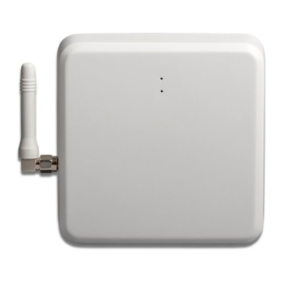
The device appearance

The first LED  indicates the pairing with the HUB and lights in two colours:
- Green light to signify the switch is paired with SmartHub,
- Red to signify the switch is not connected to the SmartHub.
The second LED  indicates relay status:
During normal operation flashes every 10 seconds:
- Green, if the relay is on (closed contacts: COM-NO, open contacts: COM-NC)
- Red, if the relay is off (closed contacts: COM-NC, open contacts: COM-NO)

Located on the Smart Switch's underside are:
 power supply connector,
 button 1,
 button 2,
 terminal block compartment,
 wall bracket,
 battery compartment.
Smart Switch location

Smart Switch should be situated far from any metal obstacles, transformers, engines, fluorescent lamps, microwave devices, refrigerators and other industrial equipment.
TEST mode of the relay
At any time (even when the relay is not paired to the control panel) you can press and hold the  button, the LED
  will light up with continuous light, in the following color:
- Green, if the relay is on (closed contacts: COM-NO, open contacts: COM-NC)
- Red, if the relay is off (closed contacts: COM-NC, open contacts: COM-NO)
- The next pressing of the button 2
![]() changes the state of the relay and the color of the diode
changes the state of the relay and the color of the diode
After 60 seconds from the last press of the button , the device will automatically return to the working mode.
You can exit the TEST mode at any point by pressing the  button.
Hot Water Tank

High voltage cables. Turn off the power before you start installation.
Turn off the power for your installation.
Connect the three-wire cable to the Smart Switch terminal block ‘ as shown in drawing bellow:

Attach wires to corresponding connections::
- black wire connect to NO
- normally open
- brown wire connect to COM
- common
- grey wire connect to NC
- normally close (optional)
Close terminal compartment with cover and turn on power in your installation.
Connect the Smart Switch to the power supply  or put two AAA 1.5V batteries in to the compartment

Registering the device
Open the WundaSmart application and log in to your Smart Hub, select the Devices from main menu and choose Add new device. Select Smart Switch for gas boiler or Smart Switch for hot water tank.
- You have 30 seconds Smart Switch. Press the button to pair the
![]() located on the Smart Switch underside and wait until the LED
located on the Smart Switch underside and wait until the LED ![]() starts emitting continuous green light. (about 8 seconds)
starts emitting continuous green light. (about 8 seconds)
 located on the Smart Switch underside and wait until the LED
  starts emitting continuous green light. (about 8 seconds)
The installed Smart Switch will appear on the device list.
Fixing to the wall (optional)
- Disconnect the bracket
![]() from the device, ’
from the device, ’

- Using two screws, fix the bracket
![]() to the wall,
to the wall,

- Reconnect the Smart Switch to the mounted wall bracket.

 from the device, ’


Technical data
| Nominal supply voltage: | 12VDC power adapter included in the set |
| Alternate supply voltage | 2×1.5 V, alkaline battery AAA type |
| Maximum transmit power | < 5 dBm e.r.p. |
| Radio communications: | 869.85MHz, two-way |
| Radio coverage: | up to 500m in an open area |
| External aerial: | yes (in the set) |
| Signaling | LED (RGB) |
| 1 SPDT Relay output | NO-COM-NC (3-way) 3A/250V AC |
| Operating temperature range: | 5–45°C (excluding condensation) |
| Degree of protection | IP20 |
| Dimensions | 98×98×28 mm (without aerial) |


Documents / ResourcesDownload manual
Here you can download full pdf version of manual, it may contain additional safety instructions, warranty information, FCC rules, etc.
Advertisement


Need help?
Do you have a question about the Smart Switch and is the answer not in the manual?
Questions and answers