Table of Contents
Advertisement
Pilot's Guide
ADVANCED ELECTRONIC INSTRUMENTATION
VM1000C
VISION MICROSYSTEMS INCORPORATED.
Information: P. O. Box 7033
Huntington Beach, CA 92646
Factory: 3183 B Airway
Costa Mesa, CA 92626
714-557-3805
www.visionmicrosystem.com
(VM1000PG023.doc)
Printed in the United States of America
Revision B 8/2007
Copyright © 2007 Vision Microsystems Incorporated
Advertisement
Table of Contents

Related Manuals for vision microsystems VM1000C

Summary of Contents for vision microsystems VM1000C
- Page 1 VM1000C VISION MICROSYSTEMS INCORPORATED. Information: P. O. Box 7033 Huntington Beach, CA 92646 Factory: 3183 B Airway Costa Mesa, CA 92626 714-557-3805 www.visionmicrosystem.com (VM1000PG023.doc) Printed in the United States of America Revision B 8/2007 Copyright © 2007 Vision Microsystems Incorporated...
-
Page 2: Table Of Contents
Table of Contents Section 1 - BASIC OPERATION Buttons Display Dimming control Tachometer Operation Manifold Pressure Operation Percent Power Operation / Calibration Oil System Operation Fuel Computer System Operation Cylinder Watch System Operation EGT Analyzer System Operation Peaking Mode Operation Electrical Monitoring System Operation Autotrack™... - Page 3 General Fuel Flow Transducer Installation Section 4 - INITIAL SYSTEM SETUP System Setup VisionConfig Setup Built-in VM1000C Setup Mandatory Setup User Setup Percent Power Operation / Calibration Fuel Level System Calibration Section 5 - CONNECTOR PIN ASSIGNMENTS Section 6 -...
- Page 4 VISION MICROSYSTEMS INCORPORATED. VISION MICROSYSTEMS INCORPORATED has made every effort to document this product accurately and completely. However, VISION MICROSYSTEMS INCORPORATED assumes no liability for errors or for damages that result from the use of this manual or the equipment it accompanies.
-
Page 5: Basic Operation
Section 1 - BASIC OPERATION Buttons There are five buttons on the front panel, referred to in this manual by— left to right—numbers 1 through 5. They function differently, depending on the mode of operation: normal, fueling or setup. Note: Button numbers are for reference only;... -
Page 6: Display
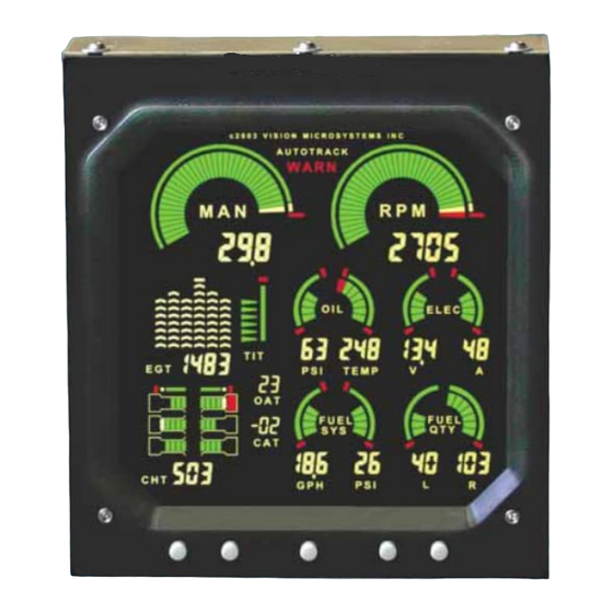
Page 2 Vision Microsystems Incorporated Display The display is the primary interface between engine instrumentation and the pilot. See the figure at the end of the table of contents for a depiction of the display. Optional measurements that are not installed will not be on the display;... -
Page 7: Manifold Pressure Operation
Note: If %HP icon is shown, then the VM1000C is in percent power mode. To change to the Manifold Pressure mode simply in until you see the MAN icon appear. -
Page 8: Percent Power Operation / Calibration
Page 4 Vision Microsystems Incorporated Percent Power Operation / Calibration The percent power system provides both a full sweep color graphic analog display and three place digital display. The full color range marks provide you with a quick reference when making fast power changes and the digital readout provides precise information. -
Page 9: Fuel Computer System Operation
VM1000C Pilot’s Guide Page Oil temperature is displayed both graphically and digitally. As oil temperature rises, the digital value and graph size increases proportionately. Temperature is displayed in either Fahrenheit or Celsius units (as set in the MISCELLANEOUS menu). The full color range marks let you see at a glance how close to red line oil temperature you are. - Page 10 Page 6 Vision Microsystems Incorporated you to see small variations and make notations of typical fuel pressure behavior. Fuel Pressure Alert warning system will flash should fuel pressure fall outside of the limits (as set in ENGINE LIMITS menu) for your particular engine.
-
Page 11: Cylinder Watch System Operation
VM1000C Pilot’s Guide Page HRS: This mode displays the calculated hours of fuel remaining (sometimes referred to as endurance), as a function of the current flow rate and current fuel remaining (REM) in the computer's memory. It is digitally displayed in 0.1 hour increments. -
Page 12: Egt Analyzer System Operation
Page 8 Vision Microsystems Incorporated Lycoming engines during setup. Full color graphics make detection of cylinder operating status easy. The digital display defaults to the hottest CHT. For example, if CHT 1 is the hottest, the digital display will show H1 periodically. -
Page 13: Peaking Mode Operation
VM1000C Pilot’s Guide Page to select a different EGT by choosing E1, E2, E3 etc. (Note: not available when in the peak mode). Temperature is displayed in either Fahrenheit or Celsius units (as set in the MISCELLANEOUS menu). WARNING Refer to your engine operating manual for the proper techniques, temperature and precautions for leaning. -
Page 14: Electrical Monitoring System Operation
Page 10 Vision Microsystems Incorporated STEP 3: Final Mixture Adjustment Now adjust the mixture differential value accordingly to which leaning mode you initially set up, rich of peak (positive DIF) or lean of peak (negative DIF). When you have completed leaning, turn off the peak mode by pressing again. - Page 15 VM1000C Pilot’s Guide Page new level of safety to engine management: a true cockpit Early Warning System. Subtle changes may occur in engine measurements that can precede major problems. These changes are often missed by even the most attentive of pilots. Autotrack alerts you to these changes allowing you to analyze the situation and take appropriate action.
-
Page 16: Flight Data Recorder System Operation
Page 12 Vision Microsystems Incorporated Here are a few examples of Autotrack scenarios: Example 1: • You arm the Autotrack system then begin a climb. • Shortly afterwards you get an Autotrack Alert. • The CHT graphic will flash and you see that the captured point is lower than the current CHT (temperature is rising). - Page 17 RPM field decimal points begin blinking. DOWNLOAD: USB Download: • Insert your USB Flash Drive into the VM1000C USB connector • The VM1000C will change the display to o All gauges will blank out o MAN digital area will display 74.0 o RPM digital area will display NEW •...
- Page 18 Page 14 Vision Microsystems Incorporated • EzTrends Download should locate the VM1000C and show the dialog below: • Click Dump New or Dump All to begin data download • All gauges will blank out MAN digital area will display 74.1 or 74.2 •...
-
Page 19: Air Temperature System Operation
VM1000C Pilot’s Guide Page Air Temperature System Operation The OUTSIDE AIR TEMPERATURE (OAT) and CARBURETOR AIR TEMPERATURE (CAT) are digitally displayed in degrees C. Most true airspeed indicators have the temperature correction scale calibrated in Degrees C, making it easy to enter the temperature directly from the OAT display. -
Page 20: Turbo Inlet Temperature System Operation
Page 16 Vision Microsystems Incorporated display will show Er. An unusual unsteady display value should be suspect and possibly disregarded as faulty operation. Fuel Level Alert: A low fuel level alarm has been incorporated into the system which signals you when a minimum fuel level has been reached (as set in 60.0 FUEL LEVEL CALIBRATION) for a given... - Page 21 VM1000C Pilot’s Guide Page Displays the various checklist sub-categories, such as CLDSTART, TAXI, RUNUP, etc. Tap button to select a sub- topic. Tap button to choose a line in the sub-topic. VOICNOTE: Record and play back aircraft audio. REC begins recording audio.
- Page 22 STEP 5: On TERATERM select FILE, SEND FILE and open the EC100_CHECKLIST.csv file located in the C: directory. STEP 6: Observe that the file is sending and that the VM1000C is receiving (shows an increasing count in the RPM field).
- Page 23 VM1000C Pilot’s Guide Page 19 STEP 1: Hold EC100 during a fresh power-up. STEP 2: Use to select the checklist item. STEP 3: Tap to start the 2-second recording. STEP 4: Power off when you have finished.
-
Page 24: Installation
The EC100 audio out signal connects to the audio system of the aircraft. (Note: You should not connect the audio out/in lines of the VM1000C when using the EC100). The audio record and playback levels are adjusted via the small slotted trimmer potentiometer screws located in the back of the unit. - Page 25 VM1000C Pilot’s Guide Page...
-
Page 26: Routing The Wiring Harnesses
Page 22 Vision Microsystems Incorporated Routing the Wiring Harnesses Five connectors are protruding from the rear of the instrument. Connect the five wiring harnesses to the rear of the instrument and run the cables... - Page 27 VM1000C Pilot’s Guide Page 23 through the firewall into the engine compartment. Allow sufficient service loop to facilitate removal of the connectors for servicing. These wiring harnesses are labeled as follows: Conn Harness PN Measurements 790200 Oil temperature, Induction temperature,...
-
Page 28: Power Connection
Power Connection The VM1000C automatically accommodates both 14 and 28-volt electrical systems. Using the J1 connector harness 790200, connect the power lead (red) to a separate 5-amp circuit breaker connected to the master power bus. -
Page 29: Probe Wiring
VM1000C Pilot’s Guide Page 25 Probe Wiring Note: use only probes supplied with this unit. Older Vision Microsystems probes are not compatible with this instrument. When cutting the pair of leads to the proper length to connect to the probes, leave enough slack in the wiring so that probe may be interchanged to an adjacent cylinder if necessary for trouble-shooting and servicing. -
Page 30: Wiring Markings
The most common installation problems are related to poor quality terminations. Wiring Markings The VM1000C is supplied with special Teflon insulated Chromel- Alumel factory assembled wiring harness configured for the correct number of cylinders. The wire harness is marked E1= EGT-1, C1= CHT-1, etc. -
Page 31: Turbine Inlet Temperature (Tit) Probe Installation (Optional)
Cylinder Head Temperature (CHT) Probe Installation Use the J2 connector harness 700700 or 700702 labeled C1 through C4 or C6. The VISION MICROSYSTEMS probe is a bayonet probe P/N 5050-T that has a captive 3/8-24 boss that is screwed into the head of... -
Page 32: Outside Air Temperature (Oat) Probe Installation
Page 28 Vision Microsystems Incorporated For Indicator replacement, replace your existing CHT probe and adapter, a bayonet or screw in type with one supplied by VISION MICROSYSTEMS. Install the probe on the same cylinder from which you removed the original equipment probe. Your current CHT probe is installed in the hottest cylinder as determined by the airframe manufacturer. -
Page 33: Carburetor (Cat) Probe Installation (Optional)
VM1000C Pilot’s Guide Page 29 digital temperature like "125 IAT". On non-turbo engines the IAT in reality is the Carburetor temperature and displayed as “34 CRB”. Carburetor (CAT) Probe Installation (Optional) Use the J1 connector harness 700200 and insert the yellow wire into the... -
Page 34: Oil Pressure Sensor Installation
Page 30 Vision Microsystems Incorporated Oil Pressure Sensor Installation Use the J3 connector harness 790420 labeled OILP. Mount the two ring terminals to the two terminals on the sensor using the hardware screws. Mount the pressure sensor to the pressure line using a 3 to 6-inch flexible hose and fittings (not supplied) as depicted in the drawing below. -
Page 35: Rpm Sensor Installation
VM1000C Pilot’s Guide Page Use the J5 connector harness 790719-X labeled FUELP. Mount the pressure sensor to the pressure line using a 6-inch flexible hose and fittings (not supplied) as depicted in the drawing below. Use tie-wraps to mount the pressure sensor an engine mount structure. Do not mount the sensor directly to the engine. -
Page 36: Capacitive Fuel Level Sender Installation
Page 32 Vision Microsystems Incorporated ammeter configuration. The alarm will be triggered by a discharge condition. Master switch Alternator contactor - BATT + Master switch external shunt Starter Starter solenoid Ammeter Configuration Load Meter configuration. The shunt must be installed between the alternator output and the main bus. - Page 37 VM1000C Pilot’s Guide Page 33 The fuel level probes are designed to be installed in virtually all types of wing tank configurations. The basic objective are to install the probe so that it can sense the fuel level change from full tank to empty tank (i.e.
- Page 38 Page 34 Vision Microsystems Incorporated probe as the alignment guide. Bond the bushing to the rib / baffle using the techniques recommended in your aircraft construction manual. NOTE 3: End supports (white bushing) The probe end must be supported if more than 4 inches of length remains after the last support point.
-
Page 39: Resistive Fuel Level Sender Installation
Resistive Fuel Level Sender Installation Disconnect the fuel level senders from the aircraft’s existing wiring harness, and connect them to the VISION MICROSYSTEMS supplied harnesses as described below. Make sure they do not have voltage on them before connecting to the VM1000C. - Page 40 Page 36 Vision Microsystems Incorporated General Fuel Flow Transducer Installation Use the J4 connector harness 700709 labeled FFSIG (white), FFPWR (red), and FFGND (black). Follow any installation instructions included with the probe. Save your K-factor tag (tied to the transducer) as you will enter the number during initial setup in the step coded 40.6.
- Page 41 VM1000C Pilot’s Guide Page 37 Aeroquip Cut slit in fire sleeve 900591B Clamp Fittings 1/4 NPT. Do NOT MS 21919 use aluminum fittings Clamp as required Transducer Aeroquip 303 hose to carburetor, flow divider, or fuel from fuel tank, 6 inches maximum from...
- Page 42 Section 4 - INITIAL SYSTEM SETUP System Setup There are two ways to configure the parameters of the VM1000C: use the provided VisionConfig program running on a PC or directly using the built in setup menus. VisionConfig Setup Overview The VisionConfig assists you in configuring the VM1000C.
- Page 43 Save the configuration data in a file at the completion of downloading. Upload mode transfers configuration data from your PC to VM1000C. Click the Start button. The program will display the number of bytes sent. Configuring your VM1000C using your PC...
- Page 44 Page 40 Vision Microsystems Incorporated • Start Vision Configuration program. • When Vision Configuration program starts, click on the Transfer Config Data tab. • Select the desired COM port and transfer speed. • Click the upper button between the two images •...
- Page 45 The only thing you can change here is the aircraft ‘N’ number. Must be all digits (no alpha characters). Engine Tab o Use this tab to tell the VM1000C about your aircraft’s engine an transducers used to monitor the engine. o Correct transducer selection is required for proper system operation.
- Page 46 The High Red, Yellow, High Green and Low Green values describe where the gauge sweep should begin and end for the particular color. High Red (and Low Red for some gauges) signifies the engine’s “redline” limit and are used to set the VM1000C’s alarm values.
- Page 47 The Fuel Tab allows you to select gallons or liters as your preferred fuel measurement. This tab is also where you tell the VM1000C what the K- Factor of your Fuel Flow transducer is. In addition, you can view your...
- Page 48 Page 44 Vision Microsystems Incorporated VM COM Port TAB The VM COM Port tab allows you to specify communications parameters when communicating with other instruments in your aircraft. Once configured, these values are rarely change.
- Page 49 VM1000C Pilot’s Guide Page 45 Miscellaneous Data Tab The Miscellaneous Data tab allows you to control these major functions: • Brightness – Display brightness from 1 to 9 • Datalog Interval – controls how often engine values are stored in the Datalog.
- Page 50 Page 46 Vision Microsystems Incorporated Sending Data Back to VM1000C To save your changes to the VM1000C configuration, click on the lower button between the two images Vision Configuration program will send the modifications to the VM1000C and when complete the VM1000C will restart with the new values.
- Page 51 They are non case sensitive. Built-in VM1000C Setup Setup the VM1000C by performing various steps in the Setup Menu or use Vision Config. All steps within the Mandatory Setup section must be accomplished first. Next, verify your actual engine limits agree with the instrument limits by stepping through all of the ENGINE MENU limits.
- Page 52 Page 48 Vision Microsystems Incorporated To operate the Setup Menu A. After power has been off for a minimum of 2 minutes, power back up and hold until you see the first menu code displayed: 10.0. B. Tap to select to the desired menu code (example: 40.0).
- Page 53 VM1000C Pilot’s Guide Page 49 MISCELLANEOUS 40.0 40. I Lycoming or Cont 1 = Lycoming cylinder 40. I 40. I 40. I CHT numbering. number front (2,1), middle (4,3), rear (6,5). 2 = Continental cylinder number front (6,5), middle (4,3), rear (2,1) 40.2 Magneto or Electronic...
- Page 54 Page 50 Vision Microsystems Incorporated 4 I.4 MAN transducer 1 = Standard 4 I.4 4 I.4 4 I.4 2 = Kavlico 3=UMA 4 I.5 FADEC option. 0 = no fadec 4 I.5 4 I.5 4 I.5 1 = fadec 4 I.6 Number of TIT probes 0 = none 4 I.6...
- Page 55 VM1000C Pilot’s Guide Page User definable engine 50.0 50.0 * If chosen in “range marks 50.0 50.0 parameters desired” section 50. I Percent power 50. I • range marks desired 50. I 50. I • low green • high green •...
- Page 56 Page 52 Vision Microsystems Incorporated 50.6 Volts 50.6 50.6 50.6 • low red • low green • high green • high red • Autotrack tolerance • Alarm tolerance 50.7 Amps 50.7 50.7 50.7 • range marks desired • low red (if chosen*) •...
- Page 57 VM1000C Pilot’s Guide Page 53 5 5 5 5 I. I I. I I. I I. I EGT • bottom segment • top segment • Autotrack tolerance • Alarm tolerance 5 I.2 TIT 5 I.2 5 I.2 5 I.2 • low green •...
- Page 58 Page 54 Vision Microsystems Incorporated 60.4 PRIMARY left tank 60.4 60.4 60.4 alarm (cant set the alarms unless a cal has been done) 60.5 PRIMARY right tank 60.5 60.5 60.5 alarm 60.6 60.6 SECONDARY 60.6 60.6 (GROUND) left tank 60.7 SECONDARY 60.7...
- Page 59 70.6 70.6 70.6 1 = upload EC100 checklist from PC (use Teraterm to send) 2 = download the EC100 that is currently in VM1000C (use log option in Teraterm) 70.7 70.7 Download System 70.7 70.7 Configuration to PC Upload system 70.8...
- Page 60 Fuel Level System Calibration The VM1000C supports either single or dual fuel tank monitoring. Each monitored tank must have a PRIMARY CALIBRATION performed. For aircraft having a significantly different calibration reading in cruise vs. on the ground, such as taildraggers, you may optionally perform a SECONDARY CALIBRATION.
- Page 61 VM1000C Pilot’s Guide Page 57 First, prepare the tank for calibration by draining it to UNUSABLE fuel and positioning the aircraft in the desired calibration attitude - cruise attitude for the PRIMARY (required) or ground attitude (optional) for SECONDARY. These are the basic steps for each tank calibration STEP 1.
- Page 62 Page 58 Vision Microsystems Incorporated Section 5 - CONNECTOR PIN ASSIGNMENTS P1 Options 25-pin P3 MAN-RPM 9-pin P4 Fuel Flow 15-pin connector connector connector Probe or Function/ Function function sensor pin yel 1 red 2 grn 1 RPM sig /1...
- Page 63 VM1000C Pilot’s Guide Page 59 Section 6 - TECHNICAL SUPPORT Website: http://www.visionmicrosystems.com/ Email support: support@visionmicrosystems.com...
- Page 64 Page 60 Vision Microsystems Incorporated Index Configuration, 39 Connector pin assignments, 50 Cylinder numbering, 41 Adding fuel, 7 Cylinder Watch, 7 Air temperature operation, 13 Alarm volume, 41 Ammeter shunt installation, 29 Data recorder Amperes, 10 operation, 12 Amps sensor type, 42...
- Page 65 VM1000C Pilot’s Guide Page 61 Fuel adding, 7 Fuel computer Lean method, 41 operation, 5 Level Fuel flow transducer fuel, 14 installation, 34 Low fuel, 41 Fuel level Low level brightness, 42 calibration, 48 operation, 14 Fuel level calibration, 45...
- Page 66 Page 62 Vision Microsystems Incorporated operation, 4 Tachometer sensor Pin assignments installation, 29 connectors, 50 Technical support, 51 Probe list, 22 Temperature units, 41, 42 Product support, 51 Template mounting, 18 Time set, 40 Recorder operation, 14 operation, 12 TIT probe...
Need help?
Do you have a question about the VM1000C and is the answer not in the manual?
Questions and answers