Advertisement
Quick Links
Installation & Operation
Manual
SunStat® Relay II
Model 500810 (-BB, -HB)
For use only with Models 500750 and 500775
The SunStat Relay II model 500810 is designed to operate either a 120 VAC or
240 VAC resistance floor heating system in conjunction with a thermostat Model
500750 or 500775. It comes with a GFCI inside to meet safety needs.
Read this Manual BEFORE using this equipment.
Failure to read and follow all safety and use
information can result in death, serious personal
injury, property damage, or damage to the
equipment.
Keep this Manual for future reference.
Installation must be performed by qualified personnel, in accordance with
local codes and standards. A licensed electrician is recommended.
As with any electrical product, care should be taken to guard
against the potential risk of fire, electric shock, and injury to
persons. The following must be observed:
• Wire all circuits as Class 1, Electric Light and Power Circuits.
• Wire all circuits with insulation rated 600V minimum.
• Mount this control only to a grounded metallic box or a nonmetallic box.
• Use power supply wires suitable for at least 90°C.
• High voltage – disconnect power supply before servicing.
• The GFCI (ground-fault circuit interrupter) in this thermostat control does not
protect against shock if both bare conductors are touched at the same time.
• Do not exceed 15 amps on this thermostat control. Doing so will cause risk
of fire hazard and damage.
• Make sure the house power supply voltage matches the voltage rating of
the floor heating system. Do not apply 240 VAC to a 120 VAC rated system.
Connecting the wrong voltage may cause overheating and damage to the
system, the control, floor coverings, etc.
Local building or electrical codes may require modifications to the information
provided. You are required to consult the local building and electrical codes
prior to installation. If this information is not consistent with local building or
electrical codes, the local codes should be followed.
Items included
Unpack the control and make sure everything is in good condition. Do not use
a damaged control or part. The package comes with these items:
(1) Relay II control
(5) Wire Nuts (Marettes®)
(2) Mounting Screws
(1) Screwdriver
Tools and supplies needed
• 18 AWG to 24 AWG 2-conductor shielded wire
• No. 2 Phillips screwdriver
• Hole saw (if installing in an existing wall)
• Wire strippers, wire cutters, and other electrical tools
• Electrical wall box (plastic or metal)*
*A single-gang extra-deep box allows suffi cient space to connect 1 or 2 hea ng
mats or cables. For 3 hea ng mats or cables, a 4-inch square extra-deep
electrical box with a single-gang "mud ring" is necessary. Alternately, a junc on
box may be installed to connect mul ple hea ng mats or cables, then run
power supply wire from the junc on box to the control electrical box. See the
Installa on Instruc ons provided with the fl oor hea ng system for more details.
Installa on
Locating the Control
Find a suitable location for the control. Consider the following:
• It is designed for indoor dry location only.
• It may be placed on an insulated or uninsulated wall, preferably an interior
wall to avoid overheating from outside sun heat.
• Keep it away from all water sources such as sinks, showers, and bathtubs
as well as heat sources such as hot-water piping, heat ducting, wall-mount
lighting, and direct sunlight.
• Locate it at a suitable height, normally about 4-1/2' to 5' (1.4 m to 1.5 m)
from the floor.
Mounting the electrical box
• When mounting on an existing wall, cut the opening for the electrical box for
the control. To make it easier to pull the wiring, wait to install the electrical
box until after all wiring is drawn into this opening.
• When mounting on an open wall, secure the electrical box for the control to
the wall stud. Conduit from the electrical box to the floor is recommended
(check local codes for requirements) for additional protection. Install one
conduit for the floor sensor. Install another conduit for the floor heating
system power leads.
• Refer to the Installation Instructions supplied with the floor heating system
for additional installation details.
Advertisement

Subscribe to Our Youtube Channel
Related Manuals for Watts SunStat Relay II

Summary of Contents for Watts SunStat Relay II
- Page 1 For 3 hea ng mats or cables, a 4-inch square extra-deep The SunStat Relay II model 500810 is designed to operate either a 120 VAC or electrical box with a single-gang “mud ring” is necessary. Alternately, a junc on...
- Page 2 Pull 18 AWG to 24 AWG 2-conductor shielded wire through the wall from the SunStat Relay II location to this control location. This wire may be up to 100 feet (30 m) in length. Strip the wire ends 1/8" to 3/16" (3 mm to 4.5 mm) long.
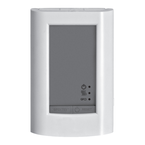
- Page 3 Operation Figure 2 Overview Power (green) Heating (amber) On/Off and Reset Pressing will turn the thermostat on or off. This also resets the thermostat to clear an error or GFCI fault. See “GFCI Testing” and “Troubleshooting”. Heating The Heating light will show amber when the control is sending power to the floor heating system.
- Page 4 This limited warranty is in lieu of all other warranties, obligations, or liabilities voltage supplied to heating system. Check for correct expressed or implied by the company. In no event shall Watts Radiant be liable for amps drawn by heating system.
Need help?
Do you have a question about the SunStat Relay II and is the answer not in the manual?
Questions and answers