Table of Contents
Advertisement
Quick Links
Automotive VBOX 3i User Guide
•
01 - VB3i Introduction
•
02 - VB3i GNSS Antenna Placement
•
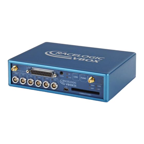
03 - VB3i Front Panel
•
04 - VB3i LED Indicators
•
05 - VB3i Logging
•
06 - VB3i Dual Antenna Setup
•
07 - VB3i VBOX Setup Overview
•
08 - VB3i CAN
•
09 - VB3i Analogue and Digital I/O
•
10 - VB3i Dynamic Modes
•
11 - VB3i DGPS / RTK
•
12-1 - VB3i IMU Integration - In-Vehicle Mounted
•
How to Mount the IMU
•
Kalman Filter Calibration
•
VB3i V3-V5 Additional IMU04 Channels
•
12-2 - VB3i IMU Integration - Roof Mounted
•
13 - VB3i Bluetooth Pairing
•
14 - VB3i Voice Tagging
•
VB3i Analogue Input PIN OUTS
•
VB3i Cable Identification
•
VB3i CAN Output
•
VB3i EC Declaration of Conformity
•
VB3i PIN OUTS
•
VB3i Technical Specification
1
Advertisement
Table of Contents

Summary of Contents for VBOX 3i
- Page 1 Automotive VBOX 3i User Guide • 01 - VB3i Introduction • 02 - VB3i GNSS Antenna Placement • 03 - VB3i Front Panel • 04 - VB3i LED Indicators • 05 - VB3i Logging • 06 - VB3i Dual Antenna Setup •...
-
Page 2: Power Supply
Power Supply Included with the VBOX 3i is a cigar lighter power cable, which is the primary source of power input. This is terminated in a 2-way connector and mates with the 2-way ‘PWR’ socket on the VBOX 3i. -
Page 3: Hardware Variants
The VBOX 3i has been designed to generate as little heat as possible, and it has a wide operating temperature range. However, it is good practice to mount the VBOX 3i in a position where it has sufficient airflow around the case. - Page 4 VB3iDR label Inputs/Outputs VBOX 3i (VB3i) https://en.racelogic.support//Product_Info/VBOX_Data_Loggers/VBOX_3i_Range/VBOX_3i_User_Guide_(All_Variants)/01_- _VB3i_Introduction...
- Page 5 VBOX 3i Dual Antenna (VB3iD) VBOX 3i RTK (VB3iDR) https://en.racelogic.support//Product_Info/VBOX_Data_Loggers/VBOX_3i_Range/VBOX_3i_User_Guide_(All_Variants)/01_- _VB3i_Introduction...
- Page 6 SI units. The analogue input connector also provides two power outputs that may be used for driving sensors. These are in the form of a 5 V DC supply and an output equal to the VBOX power supply voltage. If the VBOX is set to 100 Hz log rate, then the additional option of 500 Hz analogue data sampling will be present and available.
- Page 7 PC monitoring of test data. • USB VBOX 3i USB connector can be used for VBOX configuration and to output real-time data at 100 Hz to a PC. • Bluetooth VBOX 3i comes equipped with an internal Bluetooth Radio, allowing remote configuration and remote output of real- time GNSS data to any Bluetooth capable PC or Data logger.
- Page 8 Single Antenna Systems The GNSS antenna supplied with the VBOX is a 5 V active antenna. For the best possible signal quality, it is important to maintain a clean connection between the antenna and the VBOX. Before fixing the antenna to the VBOX, ensure that there are no dust particles in either connector.
- Page 9 This has an internal ground plane and can operate perfectly without the need for mounting on a metal surface. Ground plane antennas are available from your VBOX distributor. https://en.racelogic.support//Product_Info/VBOX_Data_Loggers/VBOX_3i_Range/VBOX_3i_User_Guide_(All_Variants)/02_-...
- Page 10 Media, iframe, embed and object tags are not supported inside of a PDF. Dual Antenna Systems For further info on slip/pitch and slip/roll setups, click here. When testing using dual antenna mode, the greater the antenna separation, the greater the accuracy of the dual antenna derived data channels.
- Page 11 Some vehicle roofs limit the potential separation value. In this case a roof mount (RLACS171) can be utilised to increase separation. Antennas should be positioned so that the gold antenna connector of primary and secondary antennas (A+B) are pointing in the same direction. This matching positioning ensures that the separation measurement is relative. We recommend you measure separation from outer edge of antenna connector A, to same outer edge of antenna connector B.
- Page 12 • In pitch alignment, the primary antenna (ANT A) should be placed towards the rear of the vehicle, and the reference antenna (ANT B) placed at the front. • When in roll alignment, the primary antenna (ANT A) should be placed to the left of the vehicle, and the reference antenna (ANT B) placed to the right.
- Page 13 A GNSS coldstart forces the GNSS engine to reset its downloaded almanac of current satellite positions. This can be useful if the VBOX 3i is having trouble locking onto satellites, which typically occurs if the VBOX 3i has not been used for several weeks or if it was last used a long distance (over one thousand miles) away from the current location.
- Page 14 After performing a GNSS coldstart leave the VBOX 3i powered up in a static location where the antenna has an unobstructed view of the sky until the ‘SATS’ LED becomes solid green. Once the VBOX3i has downloaded the new almanac it will reacquire satellites in noisy situations (such as near trees, buildings and under bridges) much quicker.
- Page 15 The LOG button will override any of the automatic logging thresholds set in the VBOX. For example, if you have set the VBOX to log all the time, the LOG button will toggle logging on and off. If you have set the VBOX to ’log only when moving’...
-
Page 16: Default Setup
The default factory settings are restored to the VBOX by pressing and holding the FUNC and LOG buttons for 5 seconds. This will put the VBOX 3i into the default factory settings; 100 Hz log rate, log continuous mode, Fixed 20 ms CAN delay, Output CAN Tx Identifiers on, Racelogic CAN on the CAN port, customer VCI CAN on the SER port, and only standard GPS channels and brake trigger event time set to log. - Page 17 The CAN Bus ports A and B are located in the VBOX 3i connectors “CAN” and “SER” respectively. The function of these ports is configurable by the user using VBOX Setup to toggle the Racelogic Bus profile. The Racelogic CAN bus is used for connected Racelogic modules or displays.
- Page 18 When you connect a powered up VBOX 3i to your PC with the supplied USB lead, your PC will recognise the presence of new hardware and open the typical Windows install window for new hardware. Follow the on screen prompts and point the Windows installation to the location of your drivers.
- Page 19 04 - VB3i LED Indicators SATS • Flashing indicates no satellites in view • Flashing green sequence indicates the number of GPS satellites currently being tracked. Each flash indicates a satellite with a short pause between each sequence. • Flashing orange sequence indicates the number of GLONASS Satellites currently being tracked.
- Page 20 Only when the filter is initialised and movement is detected will the SAT LED return to its normal operation. The user will need to leave 1 minute after powering the VBOX on with the IMU connected before starting to move. This occurs on every power up of the VBOX unit.
- Page 21 IMU integration status. Only when the filter is initialised and movement is detected will the SAT LED return to its normal operation. The user will need to leave 1 minute after powering the VBOX on with the IMU connected before starting to move. This occurs on every power up of the VBOX unit.
-
Page 22: Logging Modes
With ‘log only when moving’ ticked then the VBOX will only log data to the CF card when it detects speed >0.5 km/h. Advanced The advanced logging option on the VBOX 3i allows any of the logged data channels to be used to trigger the logging on the VBOX. - Page 23 - Do not remove the CF card or power down whilst the CF LED is flashing. If you need to remove the card or power down whilst the CF LED is flashing, then press the LOG button first to stop the VBOX logging.
-
Page 24: Antenna Separation
06 - VB3i Dual Antenna Setup VBOX Manager has been developed to control the operating functions of a VB3iD/VB3iDR. This section describes how to setup your vehicle with two antennas using the 'Dual Antenna' section within the 'Setup' menu. Menu Within the 'Dual Antenna' menu, select 'Dual Antenna Mode', scroll to 'Enable' and select in order to see the full dual antenna system menu. - Page 25 2D distance between the antennas as viewed from above. It is not the straight-line distance between the antennas, regardless of the mounting angle. Note: Whenever the physical antenna separation is altered, this should be changed accordingly within VBOX Manager. Roll Mode (optional) The VB3iD/VB3iDR allows the user to separately test roll and pitch measurements during their testing.
-
Page 26: Align Antennas
To measure the slip angle with the most precision, try and get the alignment of the antennas as close as possible to the centreline of the vehicle. Any residual errors in this alignment can be removed using the 'Auto Align' feature available in VBOX Manager. The calibration process requires the driver to drive in a straight line for a short period of time, whilst maintaining a constant speed, greater than 25 km/h. - Page 27 In Dual Antenna mode you may wish to take slip measurements from other locations on the vehicle, for instance the centre of gravity or slip over the wheels. This can be set using the Slip Translation function in VBOX Manager. The five additional locations are set using Ahead/Behind and Left/Right offsets from the primary antenna location (antenna 1 in the picture below).
- Page 28 In section 1 on the diagram below there is a Left offset between the primary antenna and the target area for slip measurement. Same again for section 2, there is an Ahead offset. These offsets will need to be applied by VBOX Manager.
- Page 29 Each calculated slip point will require two offsets, Ahead/Behind and Left/Right for the VBOX to calculate the channels correctly. Note: If the primary antenna moves, the offsets will need to be measured again, for example swapping between a pitch and roll setup.
- Page 30 Once physically connected and powered, open the software and use the drop down list to select the correct COM port that the VB3i is connected to. VBOX Setup automatically connects to the selected device and enters the VB3i setup screen.
-
Page 31: Software Overview
Note: An auto detect message may appear if the baud rate has been changed from the default value – select ‘Yes’ to allow the different baud rates to be scanned. Software Overview 1. Menu - The side bar allows selection between the different settings menus. Click the buttons to change. 2. -
Page 32: General Menu
3. Help - Depending on which menu is open, selecting the question mark icon will open up the corresponding User Guide page within the Racelogic Support Centre. 4. Bus usage - View serial and CAN channel usage. 5. Language - Select an operating language. 6. - Page 33 https://en.racelogic.support//Product_Info/VBOX_Data_Loggers/VBOX_3i_Range/VBOX_3i_User_Guide_(All_Variants)/07_- _VB3i_VBOX_Setup_Overview...
- Page 34 Racelogic modules (i.e. TC8, FIM03 etc), and displays such as VBOX Manager and Multi-Function Display. This port will allow the VBOX 3i to log up to a maximum of 32 Racelogic module channels.
- Page 35 CAN channel availability – send over serial Same as the MFD, a data channel must be in the first 32 CAN channel ordering for the VBOX 3i to send out data over serial to a ‘live data window’ on VBOX Test Suite.
- Page 36 It is possible to output channel data from the Racelogic CAN bus (i.e. Racelogic modules such as TC8) on the isolated customer VCI bus. The user can configure output data (in VBOX Setup) using channels from the available channels dropdown list, and configure the identifier as required.
- Page 37 Note: These output CAN channels will be in a 32 bit IEEE float format. 29 bit extended identifiers optional. VB3i CANVEL If an input channel is given the name 'CANVEL', then the VBOX will translate the data of this channel directly through to the GPS speed channel under the following criteria.
- Page 38 VBOX will recognise the following unit names: MPH, KM/H, Knots, m/s, and ms-1. Note: If no UNITS have been assigned to the input channel then VBOX will assume that it is KM/H. This function is useful while testing around built up areas or driving under large bridges.
- Page 39 does not follow. So you should check that the Termination is correctly set for the output socket that you are then using. VB3i CAN Delay When to Use the Fixed CAN Delay? ‘Fixed CAN Delay’ is recommended for use when using an external event marker or trigger, or for other external CAN devices that require precisely timed CAN outputs.
- Page 40 Fixed CAN Delay Example Minimum CAN Delay Example https://en.racelogic.support//Product_Info/VBOX_Data_Loggers/VBOX_3i_Range/VBOX_3i_User_Guide_(All_Variants)/08_- _VB3i_CAN...
- Page 41 CAN Delay with IMU Integration When IMU Integration, the CAN Delay is automatically set to ‘Fixed’; the speed and position delay is 20 ms. IMU Integration CAN Delay Example ADAS Modes Fixed • Static Point and Lane Departure: 20 ms; Total delay: 20 ms. •...
-
Page 42: Analogue Inputs
The analogue input connector also contains voltage outputs that can be used to power external sensors. These are a Vbatt connection which is equal to the VBOX input voltage level and a 5 V DC out connection which is equal to 5 V ±2%. - Page 43 In this case, changing the scale and offset to suit the sensor data sheet allows the data stored onto the compact flash to be in kg. When changing settings for an analogue channel using VBOX Setup software, a live data view of the current channel is shown.
- Page 44 When loading the VBO file into VBOX Test Suite, ensure you are running the very latest version as older versions are not compatible with 500 Hz data. Within VBOX Setup, the 500 Hz option is available within the 'Logging' settings, as shown below.
-
Page 45: Digital Inputs
Digital Inputs The ‘D IN’ connector contains the two digital inputs for the VBOX 3i. Digital input 1 is also referred to as the brake trigger input. This input is connected to an event capture input on the GPS engine. This captures precisely the trigger event time (10 ns resolution) for use in brake distance calculation. - Page 46 Two digital inputs devices can be connected to the VBOX 3i with the use of an additional splitter box, as shown in the image below. https://en.racelogic.support//Product_Info/VBOX_Data_Loggers/VBOX_3i_Range/VBOX_3i_User_Guide_(All_Variants)/09_- _VB3i_Analogue_and_Digital_I%2F%2FO...
- Page 47 AD1 is a simple on/off state output. This digital output can be associated with any of the data channels being logged by the VBOX. A threshold level can be set for the selected data channel where a true condition gives a 5 V output and a false condition gives a 0 V.
- Page 48 10 - VB3i Dynamic Modes The VBOX has three dynamic modes. These dynamic modes directly change the SMI smoothing index applied by the GPS engine to all Doppler-derived data, notably speed and heading. The lower smoothing levels have a higher dynamic response but are adversely noisier.
- Page 49 For more information on what DGPS is and how it works, click here. For more information on RTK, click here. VBOX 3i now supports an RTK connection using NTRIP. For more information on how this is set up, click here. How to enable DGPS Modes...
- Page 50 2. Select the correct DGPS mode from the available options. 3. Select 'Back' and then select 'DGPS Rate' within the 'VBOX' menu. 4. Choose the correct DGPS baud rate from the available options. 5. Select 'Exit' to return to main menu.
- Page 51 40 cm positional accuracy: If the VBOX 3i is used with a RTCM v2 enabled Base Station then the positional accuracy is increased to 40 cm 95 % CEP. The height accuracy is improved to 1 m 95 % CEP.
-
Page 52: Fixed Position
Solution Type Definition RTK Float RTK Fixed Fixed position IMU Coast (Kalman Filter) 0 = None GNSS receiver cannot compute a solution for position. 1 = GNSS only Position computed from GNSS only. 2 = GNSS DGPS Position computed from assisted GNSS, this includes SBAS and Base Station DGPS corrections. 3 = RTK Float Position computed from GNSS corrected by RTK. -
Page 53: Required Equipment
• RLCAB069L / RLCAB015L / RLACS182L - vehicle CAN bus cable (optional for wheel speeds) Setup Hardware Important note: IMU04 must be connected to VB3i before power is applied to ensure data is correctly synchronised. 1. Fit the VBOX 3i into the test vehicle, and mount the IMU as described here. https://en.racelogic.support//Product_Info/VBOX_Data_Loggers/VBOX_3i_Range/VBOX_3i_User_Guide_(All_Variants)/12-1_- _VB3i_IMU_Integration_-_In-Vehicle_Mounted... - Page 54 *When using a twin antenna system, these measurements must be taken from the main antenna (A). 4. IMU04 – Connect CAN/KF port to VBOX 3i V3-V5 25W D analogue input port using RLCAB119 cable. IMU03 – Connect either port on IMU to VBOX RL CAN port using RLCAB005-CS cable.
- Page 55 7. Enter the distances measured between the IMU and antenna A, more information on this can be found here. 8. If you would like to translate the data from the IMU location to another point on the vehicle where all measurements will be made, enter the x,y,z offset values from the required translation point to the IMU, more https://en.racelogic.support//Product_Info/VBOX_Data_Loggers/VBOX_3i_Range/VBOX_3i_User_Guide_(All_Variants)/12-1_- _VB3i_IMU_Integration_-_In-Vehicle_Mounted...
- Page 56 information on this can be found here. 9. If using IMU04, Internal IMU Attitude channels (Head_imu, Pitch_imu, Roll_imu, Pos.Qual., Lng_Jerk, Lat_Jerk and Head_imu2) will automatically be set to log. If IMU Attitude data is required to be displayed as a Live Serial data display then the user must tick the channels for 'Send over serial'.
- Page 57 11. Select 'Write to unit' to upload settings to VB3i. 12. Perform initialisation and full calibration procedure before commencing testing. VBOX Manager 1. Ensure IMU04/03 is connected, and the VBOX 3i is powered on. 2. Connect VBOX Manager to the VBOX. 3. Enter the 'SETUP' menu of VBOX Manager.
- Page 58 6. Scroll to the 'Roof Mount' menu and ensure it is 'Disabled'. 7. Select 'Ant to IMU Offset' and enter the distances measured between the IMU and antenna A, more information on this can be found here. 8. If you would like to translate the data from the IMU location to another point on the vehicle where all measurements will be made, Select 'IMU to Ref.
- Page 59 9. Internal IMU Attitude channels (Head_imu, Pitch_imu, Roll_imu, Pos.Qual., Lng_Jerk, Lat_Jerk and Head_imu2) will automatically be set to log. If IMU Attitude data is required to be displayed as a Live Serial data display (with VBOX Test Suite), then the user must enter VBOX Setup Software and tick the channels for 'Send over serial'.
-
Page 60: Important Notes
Important notes 1. To use IMU04 integration, a VB3i-V3, V4 or V5 must be used. This is an IMU04 enabled VBOX 3i unit. 2. IMU04 cannot be used with IMU integration if it is connected to a VBOX via CAN (RLCAB120 / RLCAB005-CS). - Page 61 5. Select 'Enabled' within the 'Wheel speed input' section. 6. Enter the Antenna to wheel reference point offsets, these are the x,y,z distances (m) between wheel speed reference point and the antenna. The reference point is the centre point between the rear wheels, as shown in the image below.
- Page 62 7. Use the Wheel speed 1 and 2 'Configure' buttons to open up the CAN setup area where you can load in a .dbc file or manually set up the CAN parameters by selecting the 'User' option. Alternatively, selecting 'Vehicle database' enables you to browse the Racelogic Vehicle CAN database within the software and select your vehicle.
- Page 63 8. Select 'Write to unit' to save the settings. VBOX Manager 1. Ensure IMU04 is connected via RLCAB119, and the VBOX 3i is powered on. 2. Connect VBOX Manager to the VBOX. 3. Enter the 'SETUP' menu of VBOX Manager.
- Page 64 IMU is first connected to the VBOX after being set up. This will be run through automatically after the VBOX has successfully gained satellite lock. When the IMU LED on VB3i front panel has turned a flashing green, the initialisation is complete. Note, if you are using a VB3i-V1, which has no IMU LED, read the LED indicators section below for LED behaviour.
- Page 65 Only when the filter is initialised and movement is detected will the SAT LED return to its normal operation. The user will need to leave 1 minute after powering the VBOX on with the IMU connected before starting to move. This occurs on every power up of the VBOX unit.
- Page 66 How to Mount the IMU Option 1: Roof-Mounting (Recommended) The easiest method of mounting the IMU is by placing it directly on the vehicle roof, co-located with the GPS antenna. Magnetic base (RLACS216) A specially designed IMU Roof Mount (RLACS216) allows for an IMU04 (only) to be securely fastened within the machined enclosure while it's magnetic base ensures that it stays safely in place.
- Page 67 Suction mount with dual antenna pole fixing (RLACS257) If you are testing with a VBOX 3i Dual Antenna and are looking for a maximum antenna separation*, the use of Roof Mounting Pole (RLACS171) in combination with...
- Page 68 Please contact vbox@racelogic.co.uk for more information, or to order an IMU Roof Mount. https://en.racelogic.support//Product_Info/VBOX_Data_Loggers/VBOX_3i_Range/VBOX_3i_User_Guide_(All_Variants)/12-1_- _VB3i_IMU_Integration_-_In-Vehicle_Mounted/How_to_Mount_the_IMU...
-
Page 69: Mounting Suggestions
Offset' action should be used to compensate the IMU attitude angle channels (Pitch angle, roll angle). This is performed from VBOX Manager. Be aware that when mounting the IMU on an angle, that the raw accelerometer and gyro data will be incorrect, as the channels are not pitch compensated. - Page 70 Measuring Translation Points Customer required translation measurements should be made in the same plane as to which the IMU is mounted (i.e. perpendicular to the IMU base, not straight down to the ground). Important notes when using ADAS Setup 1. If using IMU filter with ADAS mode, the GPS antenna and IMU must be co-located (roof mount) or positioned so there is no relative X or Y offset between them.
-
Page 71: Option 3: Fixed Mounting
Both ends are fixed to an 8 cm x 13 cm plate which sits on a joint to accommodate for uneven surfaces. Pressed against the IMU on the floor and the vehicle's ceiling, the mounting prop ensures that the IMU is fixed tightly. Please contact vbox@racelogic.co.uk for more information or to order a mounting arm (RLACS212) Option 3: Fixed Mounting It is also possible to fix the IMU firmly to the body of the vehicle, mid-way along the wheelbase. - Page 72 IMU in relation to the antenna* to at least within +/- 5 cm. These distances must then be entered into the VBOX via either VBOX Setup or using VBOX Manager. These measurements are required when using either an IMU04 or an IMU03 unit.
-
Page 73: Recommended Procedure
Kalman Filter Calibration When using the IMU Kalman Filter, it is important to perform the full calibration procedure before meaningful testing commences. The calibration procedure is a series of specific manoeuvres that should be performed to help the Kalman filter characterise the outputs from the IMU. If the calibration procedure is not performed, the Kalman filter will still function, but may not produce the high level of accuracy until dynamic manouevres in the X and Y plane have been performed (i.e. - Page 74 Note: Using an external power backup stops the system shutting down under temporary power loss. • ‘VBOX Setup' software is used to read IMU settings. • 'VBOX Setup' software is used to read VBOX settings. • Modes change using VBOX Manager.
- Page 75 • A GPS Coldstart is performed. What happens if this isn’t done? If this procedure cannot be carried out as above then the speed accuracy will be reduced, especially for the first few minutes until the Kalman Filter is able to calibrate itself. We strongly recommend that the Kalman Filter is calibrated when carrying out high dynamic tests.
- Page 76 VB3i V3-V5 Additional IMU04 Channels IMU Attitude When using IMU04 integration with a VB3i V3-V5, there are seven IMU attitude channels which can be logged. Body angle channels heading, pitch and roll, along with acceleration rate of change channels are calculated from IMU derived data.
- Page 77 RMS Channels These four channels are for diagnostic purposes only and cannot be turned on or off. They show the noise which is present on the vertical and horizontal speed channels, as calculated by the VB3i GPS engine. The RMS (root mean square) channels which will be logged are listed below. RMS_HPOS RMS_VPOS RMS_HVEL...
- Page 78 3 cm is subtracted from the physical measurement. Translation measurements need to be made in all 3 axis, X, Y and Required equipment • VB3i (IMU04 ready) • IMU04 • RLCAB119 VBOX – IMU connecting cable • RLCAB001 / RLCAB066-2 – VB3i PC connection cable • VBOX Setup Software • VBOX Manager (optional) https://en.racelogic.support//Product_Info/VBOX_Data_Loggers/VBOX_3i_Range/VBOX_3i_User_Guide_(All_Variants)/12-2_-...
- Page 79 2. Connect antenna from IMU roof mount to the primary antenna of the VB3i (antenna A). 3. Connect RLCAB119 cable from left hand port on roof mount IMU (CAN/KF) to VBOX 3i V3-V5 25W D analogue input port. 4. Take data translation measurements in X, Y and Z axis from centre of IMU, if required. Default 1 m under IMU.
- Page 80 1. Ensure IMU04 is connected via RLCAB119, and the VBOX 3i is powered on. 2. Connect VBOX 3i to a computer either via Bluetooth, an RLCAB001 cable to the 'SER' input and the computer's serial port (usb-serial adapter may be required), or via an RLCAB066-2 cable to one of the computer's USB ports.
- Page 81 8. The Internal IMU Attitude channels (Head_imu, Pitch_imu, Roll_imu, Pos.Qual., Lng_Jerk, Lat_Jerk and Head_imu2) will automatically be set to log. If IMU Attitude data is required to be displayed as a Live Serial data display then the user must tick the channels for 'Send over serial'. https://en.racelogic.support//Product_Info/VBOX_Data_Loggers/VBOX_3i_Range/VBOX_3i_User_Guide_(All_Variants)/12-2_- _VB3i_IMU_Integration_-_Roof_Mounted...
- Page 82 11. Perform initialisation and full calibration procedure before commencing testing. VBOX Manager 1. Ensure IMU04 is connected via RLCAB119, and the VBOX 3i is powered on. 2. Connect VBOX Manager to the VBOX. 3. Enter the 'SETUP' menu of VBOX Manager.
- Page 83 6. Scroll to the 'Roof Mount' menu and select. 7. Choose 'Enable' and select. Once the 'OK' confirmation screen has cleared, 'Enabled' will be displayed. 8. If required, select 'IMU to Ref. Offset' and enter distances to translate the IMU location to another point within the vehicle, more information on this can be found here.
- Page 84 9. Internal IMU Attitude channels (Head_imu, Pitch_imu, Roll_imu, Pos.Qual., Lng_Jerk, Lat_Jerk and Head_imu2) will automatically be set to log. If IMU Attitude data is required to be displayed as a Live Serial data display (with VBOX Test Suite), then the user must enter VBOX Setup Software and tick the channels for 'Send over serial'.
- Page 85 Important notes 1. To use IMU04 integration, a VB3i-V3, V4 or V5 must be used. This is an IMU04 enabled VBOX 3i unit. 2. IMU04 cannot be used with IMU integration if it is connected to a VBOX via CAN (RLCAB120 / RLCAB005-CS).
- Page 86 5. Select 'Enabled' within the 'Wheel speed input' section. 6. Enter the Antenna to wheel reference point offsets, these are the x,y,z distances (m) between wheel speed reference point and the antenna. The reference point is the centre point between the rear wheels, as shown in the image below.
- Page 87 7. Use the Wheel speed 1 and 2 'Configure' buttons to open up the CAN setup area where you can load in a .dbc file or manually set up the CAN parameters by selecting the 'User' option. Alternatively, selecting 'Vehicle database' enables you to browse the Racelogic Vehicle CAN database within the software and select your vehicle.
- Page 88 8. Select 'Write to unit' to save the settings. VBOX Manager 1. Ensure IMU04 is connected via RLCAB119, and the VBOX 3i is powered on. 2. Connect VBOX Manager to the VBOX. 3. Enter the 'SETUP' menu of VBOX Manager.
- Page 89 IMU is first connected to the VBOX after being set up. This will be run through automatically after the VBOX has successfully gained satellite lock. When the IMU LED on VB3i front panel has turned a flashing green, the initialisation is complete.
- Page 90 Initial boot up phase No coms Temperature checks. If temperature Using IMU integration, inertial data Orange outside optimum operation range, being sent to host VBOX via RS232. LED will remain orange. Inertial data being sent to host Green Fully operational. system via CAN.
- Page 91 The VBOX 3i comes equipped with a Bluetooth radio allowing configuration of the VBOX remotely along with remote output of real-time VBOX 3i serial data, at the full 100 Hz data rate, to any Bluetooth capable PC or Data logger.
- Page 92 14 - VB3i Voice Tagging The VBOX 3i has the ability to record audio tags synched with a set GPS timestamp, with an accuracy of 0.5 seconds along with the .vbo data file. Voice notes regarding test conditions or erroneous runs can be recorded, which can be...
- Page 93 For PIN out information on other VB3i ports, click here. V4/V5 View of Sub-D 25-way socket Note: A screw terminal connector block is available to purchase on request from your VBOX supplier. In / Out Description Range 1.8 M Ohms input...
- Page 94 In / Out Description Range 1.8 M Ohms input Isolated Channel 4 - impedance 9 - 10 1PPS Output -IMU04 RS232 TxD -IMU04 RS232 RxD -IMU04 Equal to Input Voltage. Vbatt 300 mA Ground 5 V Out Isolated 5 V ±2%. 120 mA Ground ISO-GND Isolated Ground...
- Page 95 View of Sub-D 25-way socket Note: A screw terminal connector block is available to purchase on request from your VBOX supplier. In / Out Description Range Channel 1 + Channel 1 - Channel 2 + Channel 2 - Channel 3 +...
- Page 96 In / Out Description Range Ground 18-25 https://en.racelogic.support//Product_Info/VBOX_Data_Loggers/VBOX_3i_Range/VBOX_3i_User_Guide_(All_Variants)/15_- _VB3i_Technical_Properties/VB3i_Analogue_Input_PIN_OUTS...
- Page 97 View of Sub-D 25-way socket Note: A screw terminal connector block is available to purchase on request from your VBOX supplier. In / Out Description Range Channel 1 + Channel 1 - Channel 2 + Channel 2 - Channel 3 +...
- Page 98 View of Sub-D 25-way socket Note: A screw terminal connector block is available to purchase on request from your VBOX supplier. In / Out Description Range Channel 1 + Channel 1 - Channel 2 + Channel 2 - Channel 3 +...
- Page 99 VB3i Cable Identification Click here for a printable PDF. https://en.racelogic.support//Product_Info/VBOX_Data_Loggers/VBOX_3i_Range/VBOX_3i_User_Guide_(All_Variants)/15_- _VB3i_Technical_Properties/VB3i_Cable_Identification...
-
Page 100: Motorola Format
VB3i CAN Output The VBOX 3i has a CAN output which is present on the 5-way connector output. Note: Channels highlighted in BLUE are present on Dual Antenna systems only. The CAN outputs for ADAS Modes are available below: •... - Page 101 Data Bytes (16) 0x305 (14) Distance (m) (15) Trigger_Time Trigger_Speed (kts) (17) 0x306 (18) True_Heading (°) (19) Slip_Angle (°) (20) Pitch_Angle (°) Speed_Quality (km/h) (24) (21) 0x307 (22) Yaw_Rate (°/s) (23) Roll_Angle (°) Longitudinal_Velocity Lateral_Velocity (km/h) (km/h) https://en.racelogic.support//Product_Info/VBOX_Data_Loggers/VBOX_3i_Range/VBOX_3i_User_Guide_(All_Variants)/15_- _VB3i_Technical_Properties/VB3i_CAN_Output...
- Page 102 Diff_Age VBOX_Type *Default Identifiers. The identifier values can be changed using the configuration software. **When IMU integration is enabled via VBOX Manager, ID 0x323 will not be selected to transmit. ***Update rate depends on GPS update rate. 10 ms Update rate shown corresponds to 100 Hz GPS setting.
- Page 103 0.01 m per bit, signed. 8. Vertical Velocity, 0.01 m/s per bit, signed. 9. Status. 8 bit unsigned char. Bit 0 = VBOX Lite, Bit 1 = Open or Closed CAN Bus (1=open), 2 = VBOX3, Bit 3 = Logging Status.
- Page 104 55. Differential Age - unsigned char, (s) differential age (0xFF = invalid). 56. Serial Number - 20 bit, VBOX serial number. 57. VBOX Type - VB3i = 1, VB3iS = 2, VBOX Omega = 3. Intel Format These channels are for use with Stahle robot systems.
- Page 105 Channel definitions are available here. Data Bytes 0x066 (1) Velocity (km/h) Unused 0x06B (2) IMU_roll_rate (°/s) (3) IMU_pitch_rate (°/s) (4) IMU_yaw_rate (°/s) Unused 0x075 (5) Long_acc (g) (6) Lat_acc (g) (7) IMU_Z_accel (g) Unused 0x083 (8) Inverse_path_radius (9) Slip_angle Unused 0x095 (10) Roll_imu (11) Pitch_imu...
- Page 106 16. Position, Position, Longitude in degrees. This is a true 32 bit signed integer, East being positive, 1e^-7 per bit. 17. X Velocity (car frame), 16 bit signed integer 0.005 m/s per bit. X Velocity = Speed(m/s) * Cos(slip angle). 18.
- Page 107 VB3i EC Declaration of Conformity https://en.racelogic.support//Product_Info/VBOX_Data_Loggers/VBOX_3i_Range/VBOX_3i_User_Guide_(All_Variants)/15_- _VB3i_Technical_Properties/VB3i_EC_Declaration_of_Conformity...
- Page 108 https://en.racelogic.support//Product_Info/VBOX_Data_Loggers/VBOX_3i_Range/VBOX_3i_User_Guide_(All_Variants)/15_- _VB3i_Technical_Properties/VB3i_EC_Declaration_of_Conformity...
- Page 109 VB3i PIN OUTS Please note that there are differences between VBOX3i V1/V2/V3/V4 and V5 versions relating to connectors 2 and 3. Details below. For PIN information on the analogue input connector, click here. Front View of VB3iD (V2 - V5) https://en.racelogic.support//Product_Info/VBOX_Data_Loggers/VBOX_3i_Range/VBOX_3i_User_Guide_(All_Variants)/15_- _VB3i_Technical_Properties/VB3i_PIN_OUTS...
- Page 110 Connector 1 - POWER (Lemo 2 PIN) Function Range Power+ 7 – 30 V Ground https://en.racelogic.support//Product_Info/VBOX_Data_Loggers/VBOX_3i_Range/VBOX_3i_User_Guide_(All_Variants)/15_- _VB3i_Technical_Properties/VB3i_PIN_OUTS...
- Page 111 Connector 2 / 3 - AD 1 / AD 2 (Lemo 3 PIN) One Analogue and One Digital Output Each V1/V2/V3 Function Range Analogue Out 1 / 2 0 – 5 V Digital Out 1 / 2 0 – 5 V Analogue Ground Shell Digital Ground...
- Page 112 Connector 4 - D IN (Lemo 3 PIN) Function Range Ground Digital Input 2. Logging 0 – 5 V (14 V tolerant) on/off Digital Input 1. Brake 0 – 5 V (14 V tolerant) Trigger https://en.racelogic.support//Product_Info/VBOX_Data_Loggers/VBOX_3i_Range/VBOX_3i_User_Guide_(All_Variants)/15_- _VB3i_Technical_Properties/VB3i_PIN_OUTS...
- Page 113 Connector 5 - CAN (Lemo 5 PIN) Function Range RS232 Tx (PORT B) +/- 12 V RS232 Rx (PORT B) +/- 12 V CAN High (PORT A) CAN Low (PORT A) +V Power Same as Power + https://en.racelogic.support//Product_Info/VBOX_Data_Loggers/VBOX_3i_Range/VBOX_3i_User_Guide_(All_Variants)/15_- _VB3i_Technical_Properties/VB3i_PIN_OUTS...
- Page 114 Connector 6 - SERIAL (Lemo 5 PIN) Function Range RS232 Tx (PORT A) +/- 12 V RS232 Rx (PORT A) +/- 12 V CAN High (PORT B) CAN Low (PORT B) +V Power Same as Power + https://en.racelogic.support//Product_Info/VBOX_Data_Loggers/VBOX_3i_Range/VBOX_3i_User_Guide_(All_Variants)/15_- _VB3i_Technical_Properties/VB3i_PIN_OUTS...
- Page 115 Connector 7 / 8 - Antenna A / B Function RF Signal / Power for active Center antenna Chassis Ground https://en.racelogic.support//Product_Info/VBOX_Data_Loggers/VBOX_3i_Range/VBOX_3i_User_Guide_(All_Variants)/15_- _VB3i_Technical_Properties/VB3i_PIN_OUTS...
-
Page 116: Gps Specifications
VB3i Technical Specification All specifications refer to the most current VBOX 3i models, specifications for older models can be viewed within legacy datasheets on the VBOX Automotive Website. GPS Specifications Velocity Accuracy 0.1 km/h (averaged over 4 samples) Units km/h or mph... - Page 117 Distance Units m / ft Update rate 100 Hz Resolution 1 cm https://en.racelogic.support//Product_Info/VBOX_Data_Loggers/VBOX_3i_Range/VBOX_3i_User_Guide_(All_Variants)/15_- _VB3i_Technical_Properties/VB3i_Technical_Specification...
- Page 118 Absolute Positioning (RMS) - VB3i Single Antenna Accuracy* (Standalone) V: 1.8 m; H: 1.2 m Accuracy* with SBAS V: 1.2 m; H: 0.8 m Accuracy* with DGPS V: 0.5 m; H: 0.3 m Update rate 100 Hz Resolution 1.8 mm Absolute Positioning (RMS) - VB3iD Dual Antenna Accuracy* (Standalone) V: 1.8 m;...
- Page 119 Absolute Positioning (RMS) - VB3iDR Dual Antenna with RTK Update rate 100 Hz Resolution 1.8 mm Time Accel/Brake Test (MFD/VBOX Test Suite) Lap Timing (MFD/VBOX Test Suite) Resolution 0.01 s Resolution 0.01 s Accuracy 0.01 s Accuracy 0.01 s** Acceleration Accuracy 0.5 %...
- Page 120 Memory Compact Flash Type I Recording Time Dependent on flash card capacity*** Brake stop accuracy Accuracy ±1.8 cm https://en.racelogic.support//Product_Info/VBOX_Data_Loggers/VBOX_3i_Range/VBOX_3i_User_Guide_(All_Variants)/15_- _VB3i_Technical_Properties/VB3i_Technical_Specification...
- Page 121 <0.067° <0.047° 2.0 m <0.05° <0.035° 2.5 m <0.04° <0.028° IMU Attitude Accuracies Channels available when an IMU04 is used in conjunction with a VBOX 3i. Attitude Accuracy (RMS) Pitch angle 0.06° Roll angle 0.06° Yaw Angle 0.5° https://en.racelogic.support//Product_Info/VBOX_Data_Loggers/VBOX_3i_Range/VBOX_3i_User_Guide_(All_Variants)/15_- _VB3i_Technical_Properties/VB3i_Technical_Specification...
- Page 122 Voltage range 0 – 5 V DC Default setting Velocity (The range settings can be adjusted by the user in 0.0125 Volts per km/h (0 – 400 km/h) VBOX Tools Software) Accuracy 0.1 km/h Update rate 100 Hz Digital Frequency range DC to 44.4 kHz...
- Page 123 Digital Accuracy 0.1 km/h Update rate 100 Hz https://en.racelogic.support//Product_Info/VBOX_Data_Loggers/VBOX_3i_Range/VBOX_3i_User_Guide_(All_Variants)/15_- _VB3i_Technical_Properties/VB3i_Technical_Specification...
- Page 124 Vehicle CAN bus Can load signal data from industry standard DBC database file Channels that fall outside of the ‘standard channel tab’ Other channels within VBOX Setup e.g. AD inputs, IMU KF channels, twin antennas channels, ADAS channels Analogue Number of channels Input range ±50 V...
-
Page 125: Environmental And Physical
Environmental and Physical Input Voltage 7 – 30 V DC Power 5.5 W (maximum) Size 170 mm x 121 mm x 41 mm Operating Temperature -20°C to +60°C Weight 900 g (approximate) Storage Temperature -30°C to +80°C https://en.racelogic.support//Product_Info/VBOX_Data_Loggers/VBOX_3i_Range/VBOX_3i_User_Guide_(All_Variants)/15_- _VB3i_Technical_Properties/VB3i_Technical_Specification...
Need help?
Do you have a question about the 3i and is the answer not in the manual?
Questions and answers
My remote quit. How do I pair a new one?