Table of Contents
Advertisement
Quick Links
Advertisement
Table of Contents

Summary of Contents for DIAMON IN/RCX08-PVV
- Page 1 02/2019 Mod: IN/RCX08-PVV Production code: 19058507...
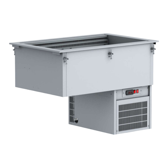
- Page 2 DROP IN REFRIGERATED VENTILATED WELL/ CUBA REFRIGERADA VENTILADA/ CUVE RÉFRIGÉRÉE FROID VENTILÉ Ref: A070200008 Vers.
- Page 3 Please check your equivalent model in the equivalent table Consulte su modelo equivalente en la tabla de equivalencias Consultez votre modèle équivalent dans le tableau d’équivalences...
- Page 4 Refrigerated ventilated well/ Cuba refrigerada ventilada/ Cuve réfrigérée froid ventilé Instruction manual Installation and Operation...
- Page 5 Anex/ Anexo/ Annexe MACHINES DRAWING ELECTRICAL & DRAIN SITUATIONS / PLANOS TÉCNICOS EN SITUACIONES ELÉCTRICAS O, DRENAJE / PLAN TECHNIQUE EN SITUATION DU ÉLECTRICITÉ OU VIDANGE Fig 1.
- Page 6 Anex/ Anexo/ Annexe Remote/ remota/ froid à distance Fig. 2...
- Page 7 Anex/ Anexo/ Annexe TECHNICAL CHARACTERISTICS / CARACTERÍSTICAS TÉCNICAS / CARACTÉRISTIQUES TECHNIQUES Model/ Capacity Dimensions Cut-Out Voltage/ Electrica Cooling Power Climatic Work Modelo (GN)/ (mm)/ Medidas Dimensions Voltaje/ Voltage l Power (W) -10ºC Tª Type/ Class/ Clase Temperatur Capacidad (mm)/ Mesures (mm)/ (W)/ evap./...
- Page 8 Anex/ Anexo/ Annexe DROP IN ASSEMBLY / MONTAJE DEL DROP IN / ASSEMBLAGE D’ENCASTREMENT Fig 3.
- Page 9 Anex/ Anexo/ Annexe DROP IN DISASSEMBLY / DESMONTAJE DEL DROP IN / DÉMONTAGE D’ENCASTREMENT Fig 4.
- Page 10 Anex/ Anexo/ Annexe CONTROL PANEL SCROLLING/ DESPLAZAMIENTO PANEL DE CONTROL/ PANNEAU DE COMMANDE DÉFILEMENT Fig. 5...
- Page 11 Anex/ Anexo/ Annexe DROP IN MAINTENANCE / MANTENIMIENTO DEL DROP IN / ENTRETIEN D’ENCASTREMENT Fig. 6...
- Page 12 Anex/ Anexo/ Annexe COLD UNIT VENTILATION/ VENTILACION DE LA UNIDAD DE FRIO/ VENTILATION DE L'UNITÉ FROIDE Fig. 7...
- Page 13 Anex/ Anexo/ Annexe CONTROL PANEL / PANEL DE MANDOS / PANNEAU DE COMMANDE Fig. 8 [10]...
- Page 14 Anex/ Anexo/ Annexe HOLE TO ASSEMBLY THE CONTROL PANEL / AGUJERO PARA INSTALAR EL PANEL DE MANDOS / LE TROU POUR ASSEMBLER LE PANNEAU DE COMMANDE Fig. 9 [11]...
-
Page 15: Table Of Contents
Instruction Manual INDEX INDEX ........................... 12 MACHINE INTRODUCTION ....................13 INTRODUCTION TO MACHINE & MODELS ..............13 IMPORTANT SAFETY INFORMATION ................13 SPECIFICATION CHART ....................13 INSTALLATION ........................14 GENERAL INFORMATION ..................... 14 TRANSPORT, HANDLING, UNPACKING, LOCATION ............. 14 INTENDED USE AND RESTRICTIONS................14 MANUFACTURER’S IDENTIFICATION LABEL DESCRIPTION. -
Page 16: Machine Introduction
Instruction Manual MACHINE INTRODUCTION 2.1 INTRODUCTION TO MACHINE & MODELS The purpose for which this equipment has been designed is to be built into a self-service buffet and is specially conceived for the display and service of cold food, maintaining the food in the best temperature condition during the period of time of the serving. -
Page 17: Installation
Instruction Manual INSTALLATION 3.1 GENERAL INFORMATION The use instructions of the digital thermostat are attached to this manual. However, WE DO NOT RECOMMEND THE ADJUSTMENT OF THE THERMOSTAT BY UNQUALIFIED PERSONNEL. Please, CONTACT YOUR DISTRIBUTOR IN ORDER TO HAVE THE NECESSARY ADJUSTMENTS CARRIED OUT. -
Page 18: Installation And Assembly
Instruction Manual Data in the identification label: Brand 2. Serial number (code+ year+ serial number) 3. Code: 4. Model: 5. CE symbol 6. Waste disposal symbol 7. Manufacturing site 8. Gas Type 9. Gas quantity (gr) 10. Climatic class 11. Working range temperature: 12. -
Page 19: Operation
Instruction Manual considerable. Therefore, it is essential to connect said outlet to the drainage network. The present appliance does not have a collection tray and automatic evaporation of said liquid. REMOTE UNIT OPTIONAL All refrigerated inlet is supplied in copper pipes, both for connecting the high pressure (liquid) and low pressure (gas) lines of the refrigeration unit are sized 3/8”. -
Page 20: Machine Settings And Programs
Instruction Manual It is possible to activate or deactivate the light output by pressing the LIGHT (6) command for 1 second. To access the sounds and alarms program (7), press and hold for more than 5 seconds. The parameter setting menu (F) will appear in the display (1) or in case of alarms, the alarm will be silenced and the alarm relay will be deactivated. -
Page 21: Maintenance
Instruction Manual The main components of the condensing unit include a hermetic compressor and an air condenser. The gas used in the cooling circuit is described in table 1 and the working pressure is approximately 2,4 and 3,2 bar depending on the model. The gas expansion at the entrance of the evaporator is carried out by means of a capillary tube. -
Page 22: Troubleshooting Chart
Instruction Manual TROUBLESHOOTING CHART 6.1 TROUBLESHOOTING CHART The appliance electric motor has a thermal protector included that trips in the event of overcurrent or lack of current. When this protector trips the appliance must be disconnected to prevent malfunctioning. Connect the appliance after an hour and contact your technical service in the event the problem remains.
Need help?
Do you have a question about the IN/RCX08-PVV and is the answer not in the manual?
Questions and answers