Table of Contents
Advertisement
Quick Links
Advertisement
Table of Contents

Summary of Contents for Datasensor DS3 Series
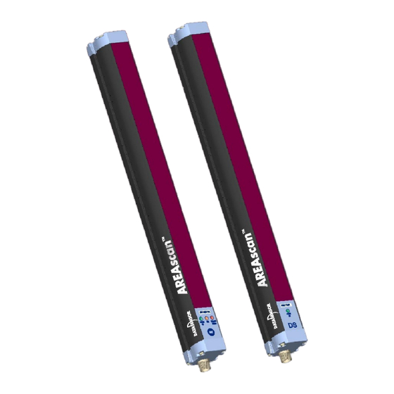
- Page 1 DS3 SERIES Object detection and measurement light grid INSTRUCTION MANUAL...
- Page 2 UNI EN IS O 1 400 1 DATASENSOR S.p.A. cares for the environment: 100 % recycle d pap er. Quality Ass uranc e Manager DATASENSOR S.p.A. reserves the right to make modificati ons an d improv ements with out prior n otificatio n.
-
Page 3: Table Of Contents
DS series Instructions manual INDEX 1. GENERAL INFORMATION ..................pag. 1 General description of the AREAscanä ä ä ä light grid........pag. 1.1. 1.2. Selecting the devic e...................pag. 1.3. Typic al applications ....................pag. 2. INSTALL ATION MODE ....................pag. 4 Precautions to be obs erved for the choic e and i nstallation of the device .pag. 2.2. -
Page 4: General Information
The variety of possibile functions makes DS3 a particularly flexible device suitable to many different applications. The AREAscan light grids of the DS3 series are manufactured in accordance with the international standards in force and in particular: CEI EN 60947-5-2: low voltage proximity switch... -
Page 5: Selecting The Device
Notes and detailed descriptions about particular characteristics of the AREAscan devices in order to better explain their functioning. DATASENSOR technical assistance is available for any necessary information related to the functioning and/or installation of the DS3 series light grids (see section 9 “Checks and periodical maintenance”). -
Page 6: Typical Applications
Instructions manual DS series 1.3. Typical applications The following images supply an overview on some of the main applications. Object detection and measurement on conveyor Control of the correct material positioning belt (opaque and transparent) during functioning (plastic, metal, paper etc) Loop control and positioning (also transparent Detection of objects w ith different shapes in the material) -
Page 7: Installation Mode
Please contact DATASENSOR Technical Service when this problem occurs. the operating distance of the device can be reduced in the presence of smog, fog or airborne dust. -
Page 8: General Information On The Device Positioning
Instructions manual DS series 2.2. General information on the device positioning • Place the device near the detection area. • Align the receiver (RX) and emitter (TX) units parallel to one another. • Fix the receiver and emitter units on rigid supports not affected by strong vibrations using the specific brackets (see section 3 “Mechanical mounting”). -
Page 9: Minimum Distance From Reflecting Surfaces
DS series Instructions manual 2.2.2. Minimum distance from reflecting surfaces Reflecting surfaces placed near the light beams of the AREAscan device (over, under or laterally) may cause passive reflections; these reflections could compromise the recognition of an object inside the controlled area (see Fig.1). - Page 10 Instructions manual DS series It is thus important to position the light grid according to the minimum distance from any reflecting surface. The minimum distance depends on: - Device operating distance - Reflecting surface nature - Position of the object inside the sensitive area The minimum distance of the reflecting object has to be: DS3-SD d >...
-
Page 11: Installation Of Several Adjacent Light Grids
DS series Instructions manual 2.2.3. Installation of several adjacent light grids When several devices must be installed in adjacent areas, care must be taken to prevent interference between the emitter of one device and the receiver of another. Fig.2 gives an example of possible interferences between different devices and two pertinent solutions. -
Page 12: Mechanical Mounting
Instructions manual DS series 3. MECHANICAL MOUNTING The emitting and receiving bars must be installed with the relevant sensitive surfaces turned towards each other; the connectors must be positioned on the same side and the distance must be included within the operating range of the model used (see section 10 “Technical data”). -
Page 13: Electrical Connections
DS series Instructions manual 4. ELECTRICAL CONNECTIONS The electrical connection between the emitter and receiver units is made through male M12 connectors, located in the lower part of the light grids. ANALOG OUTPUT ç ) D+ PNP OUTPUT NOT USED +24VDC ç... -
Page 14: Notes On The Connections
Instructions manual DS series 4.1. Notes on the connections For the correct functioning of the AREAscan light grid, the following precautions regarding the electrical connections should be taken: • Sheilded cables are not foreseen in the standard connection. However, if necessary, these cables can be used; in this case ground connection is necessary of both the unit and cable, as shown in Fig.5. - Page 15 DS series Instructions manual • The AREAscan are NOT safety devices and so MUST NOT be used to control the safety of the machines where installed. • The ground connection of the two units is not necessary. However, if required, the connection is possible; tighten the special screw – supplied with the device –...
-
Page 16: Function Selection
Instructions manual DS series 5. FUNCTION SELECTION The functions implemented in the AREAscan devices can be selected using the dip-switches inside the receiver unit as shown in Fig.7. The SET pushbutton, necessary for the calibration procedure (see section 6 “Calibration Procedure”) and teach-in function (see section 7.3 “Teach-in detection of objects”), is present on the same unit. - Page 17 DS series Instructions manual Table 1 indicates the type of function and the relative position of the dip-switches. Tab. 1 NOTE: The dip-sw itches not used are show n in grey. Black indicates the position of the dip-switch lever used.
-
Page 18: Calibration Procedure
Instructions manual DS series 6. CALIBRATION PROCEDURE The calibration procedure sets the signal level that arrives from the receiver in the rest condition (no object detection). In every other condition, the acquired signal will be compared to the one acquired during the calibration. The calibration depends on the alignment and distance of the two units;... -
Page 19: Functioning Mode
The different functioning modes available are listed below: 7.1. Scanning mode (see functions 1 and 2 of Tab.1 at page 14) Two different scanning types can be accomplished with the AREAscan of the DS3 series: • Scanning with PARALLEL beams:... - Page 20 Instructions manual DS series • Scanning w ith CROSSED beams: where several photoreceivers are illuminated by the beam of a single photoemitter (this mode activates a series of photoreceivers and one photoemitter contemporarily, during the scanning cycle). The scanning with crossed beams can be used for the detection of objects with small dimensions and, in particular, for the detection of transparent objects.
-
Page 21: Measurement Mode
DS series Instructions manual 7.2. Measurement mode 7.2.1. Absolute mode (see functions 5 and 6 of Tab.1 at page 14) Provides the measurement of the dimension of the object beginning from an absolute reference. The first photoelement is taken as a reference (1) beginning from the connector side. -
Page 22: Relative Measurement
Instructions manual DS series 7.2.2. Relative measurement (see function 7 of Tab.1 at page 14) Provides the measurement of the dimension of the object that affects the detection area independently from an absolute reference. The voltage of the analog output is proportional to the number of beams effectively obscured. -
Page 23: Object Detection Mode (Teac H-In)
DS series Instructions manual 7.3. Detection mode (teach-in) The teach-in mode can be selected using the dip-switches (see functions 9 and 10 of Tab.1 at page 14) and is active only with one of these selections. This mode allows the memorisation of the dimension of one or more objects (not adjacent) by pressing the SET pushbutton. -
Page 24: Absolute Detection
Instructions manual DS series The following operating modes can be selected using the dip-switches: 7.3.1. Absolute detection (see function 9 of Tab.1 at page 14) The digital output (PNP) switches only if a certain object (dimensions previously memorised) passe s exactly in the desired position (Fig.13). The analog output in this configuration is always active and the voltage is proportional to the number of obscured optics (also non adjacent) independently from the real switching of the digital output (PNP) -
Page 25: Relative Detection
DS series Instructions manual 7.3.2. Relative detection (see function 10 of Tab.1 at page 14) The digital output (PNP) switches each time a certain object passe s inside the sensitive area, independently from its position in the area (Fig.14). The analog output in this configuration is always active and the voltage is proportional to the number of obscured optics (also non adjacent) independently from the real switching of the digital output (PNP) caused by the object detection. -
Page 26: Dark/Light Mode Of The Output
Instructions manual DS series 7.4. DA RK/LIGHT mode of the output (see function 13 and 14 of Tab.1 at page 14) Defines the status of the digital output (PNP) and of the relative yellow signalling LED. DARK MODE Object detection Output status LED status Turned off... -
Page 27: Diagnostic Functions
DS series Instructions manual 8. DIAGNOSTIC FUNCTIONS 8.1. Visualisation of the device status The operator can verify the operating status of the DS3 device through three LEDs present on the receiver unit and one LED present on the emitter unit. The meaning of the LEDs present on the receiver unit (RX) depends on the functioning mode of the light grid. -
Page 28: Fault And Diagnostic Messages
Instructions manual DS series 8.2. Fault and diagnostic messages The operator can verify the device functioning status and the stop or failure causes of the system, using the same LEDs used for the visualisation of the functions. 8.2.1. Diagnostic mode RECEIVER UNIT Signal Cause... -
Page 29: Error Mode
DS series Instructions manual 8.2.2. Error mode RECEIVER UNIT Signal Cause Check and Repair PNP output does not switch. - Align the device again and inside the maximum operating Device failure. distance. Device aligned - Repeat the calibration outside maximum procedure. -
Page 30: Checks And Periodical Maintenance
All appliances are under a 18 month guarantee from the manufacturing date. Datasensor will not be liable for any damages to persons and things caused by the non-observance of the correct installation modes and device use. -
Page 31: Technical Data
DS series Instructions manual 10. TECHNICAL DATA Power suppl y: 24 Vdc ± 15% Consumpti on of emitter unit (TX): 100 mA max Consumpti on recei ver unit 100 mA max without load (RX): 1 PNP output; load max 10 kΩ Outputs: 1 analog output ;... -
Page 32: List Of The Avail Able Models
Instructions manual DS series 11. LIST OF AVAILABLE MODELS Response Response Length of Length of Operating N°. time of time of Model sensitiv e controlled distance beams crossed parallel area area beams beams 0.6…1.5 DS3-LD-015 msec msec 0.6…1.5 DS3-LD-030 msec msec 0.2…0.6 DS3-SD-015... -
Page 33: Overall Dimensions
DS series Instructions manual 12. OVERALL DIMENSIONS All the dimensions given are in mm. RECEIVER EMITTER...
Need help?
Do you have a question about the DS3 Series and is the answer not in the manual?
Questions and answers