Table of Contents
Advertisement
Quick Links
APPLICATION
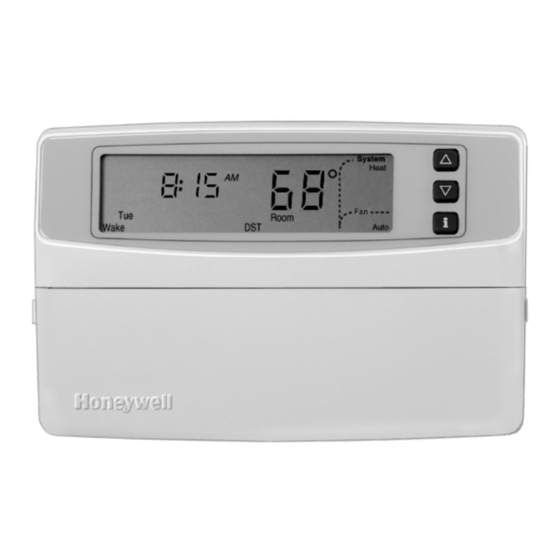
The T8535 is an electronic, nonprogrammable room thermostat that supports single-stage or multi-stage, single-zone or
multiple-zones in conventional applications. The T8535 uses the Low End SubSystem Topology (LESST), a low-cost,
wired communications protocol.
T8535
System
Changeover
L
Heat-Cool Automatic
Manual
a
Automatic changeover is not available with wired zoning applications.
RECYCLING NOTICE
If this control is replacing a control that contains
mercury in a sealed tube, do not place your old
control in the trash.
Contact your local waste management authority for
instructions regarding recycling and the proper
disposal of the old thermostat.
INSTALLATION
When Installing this Product...
1. Read these instructions carefully. Failure to follow
the instructions can damage the product or cause a
hazardous condition.
2. Check the ratings given in the instructions and on
the product to make sure the product is suitable for
your application.
3. Installer must be a trained, experienced service
technician.
4. After completing installation, use these instructions
to check out the product operation.
®U.S. Registered Trademark
Copyright © 1999 Honeywell Inc. •
Microelectronic Communicating
Nonprogrammable Thermostat
Table 1. Description of T8535 Thermostats.
System
Selection
a
/
Heat-Off-Cool-Auto
• All Rights Reserved
INSTALLATION INSTRUCTIONS
Fan
Selection
On-Auto
System and fan selections are done by
keyboard.
CAUTION
Disconnect power supply to prevent electrical
shock or equipment damage.
Location
Install the thermostat about 5 ft (1.5m) above the floor in
an area with good air circulation at average temperature.
See Fig. 1.
Do not install the thermostat where it can be affected by:
— drafts, or dead spots behind doors and in corners.
— hot or cold air from ducts.
— radiant heat from sun or appliances.
— concealed pipes and chimneys.
— unheated (uncooled) areas such as an outside wall
behind the thermostat.
Wallplate Installation
The thermostat can be mounted horizontally on the wall or
on a 2 in. x 4 in. wiring box. Position wallplate horizontally
on the wall or on a 2 in. x 4 in. wiring box.
1. Position and level the wallplate (for appearance
only). The thermostat functions properly even when
not level.
X-XX UL
T8535L
Comments
69-1307-1
Advertisement
Table of Contents

Related Manuals for Honeywell T8535L


Summary of Contents for Honeywell T8535L
- Page 1 4. After completing installation, use these instructions to check out the product operation. 1. Position and level the wallplate (for appearance only). The thermostat functions properly even when not level. ®U.S. Registered Trademark 69-1307-1 Copyright © 1999 Honeywell Inc. • • All Rights Reserved X-XX UL...
- Page 2 T8535L MICROELECTRONIC COMMUNICATING NONPROGRAMMABLE THERMOSTAT 5 FEET [1.5 METERS] M10106 Fig. 1. Typical location of thermostat. 4. Position the wallplate over the holes, pulling wires through the wiring opening. WALL 5. Loosely insert the mounting screws into the holes. 6. Tighten the mounting screws.
- Page 3 T8535L MICROELECTRONIC COMMUNICATING NONPROGRAMMABLE THERMOSTAT THERMOSTAT SUBBASE NOTE: To remove the thermostat from the wall, first pull out at the bottom of the thermostat; remove top last. Using Thermostat Keys The thermostat keys are used to: • set temperature, • display present setting, •...
- Page 4 T8535L MICROELECTRONIC COMMUNICATING NONPROGRAMMABLE THERMOSTAT The Installer Setup is used to customize the thermostat to specific systems. Some of the options include temperature display and minimum equipment off-time. Installer modes are listed in numerical order in Table 2. The table includes...
- Page 5 T8535L MICROELECTRONIC COMMUNICATING NONPROGRAMMABLE THERMOSTAT Table 2. Thermostat Installer Setup Options. Installer Setup Number Other Choices (Press i Factory-Setting (Press key to change) key to change) Scope Description Display Description Display Description Local Zone Number. Set for zone 0 1 to 15 Zone numbers can be set to (single zone).
- Page 6 T8535L MICROELECTRONIC COMMUNICATING NONPROGRAMMABLE THERMOSTAT INSTALLER SYSTEM TEST Use the Installer System Test to check the thermostat configurations and operation. Refer to Table 3 for a list of the available system tests. To start the system test: M6792A TEST NUMBER NOTE: The minimum off time for compressors is bypassed during the Installer System Test.
- Page 7 T8535L MICROELECTRONIC COMMUNICATING NONPROGRAMMABLE THERMOSTAT 4. Press the increase key again to display the Thermostat Information software revision number. (Example: 001 = revision 1. Press the Information key to access the thermo- number 1) stat information. M6791 M4864 5. Press the increase key again to display the 2.
- Page 8 T8535L MICROELECTRONIC COMMUNICATING NONPROGRAMMABLE THERMOSTAT TROUBLESHOOTING GUIDE Symptom Possible Cause Action Display does not Thermostat is not powered. Check for 24 Vac between C and R terminals; if missing 24 Vac: turn on. — Check if the circuit breaker is tripped; if so, reset the circuit breaker.
Need help?
Do you have a question about the T8535L and is the answer not in the manual?
Questions and answers