Table of Contents
Advertisement
IM(OM-8)E Rev.1
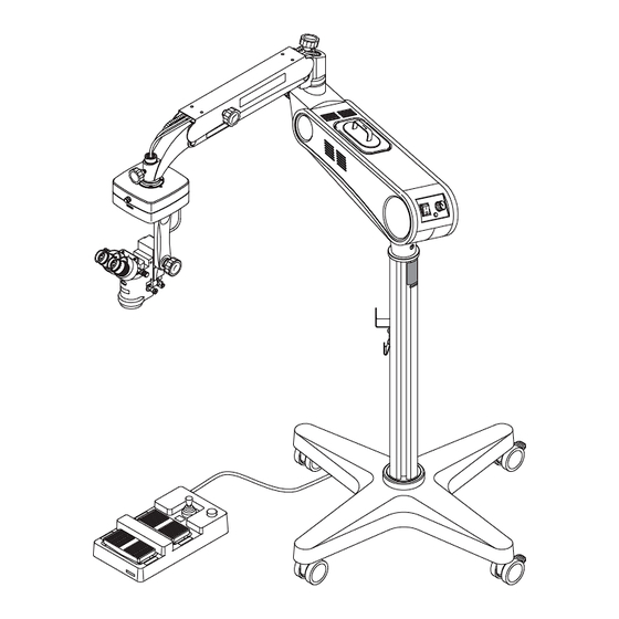
Operating Microscope
MODEL OM-8
Instruction Manual
OM8-T01
We would like to thank you for purchasing our Operating Microscope. Read
this manual thoroughly before use, understand the contents, and handle this
instrument safely and correctly
● Do not use this instrument in any other way than described in this manual.
● Keep this manual handy for future reference.
● Contact our distributor or our Sales Department if this manual is lost or
damaged.
Advertisement
Table of Contents

Summary of Contents for Takagi OM-8
- Page 1 IM(OM-8)E Rev.1 Operating Microscope MODEL OM-8 Instruction Manual OM8-T01 We would like to thank you for purchasing our Operating Microscope. Read this manual thoroughly before use, understand the contents, and handle this instrument safely and correctly ● Do not use this instrument in any other way than described in this manual.
-
Page 3: Classification Of Devices
■ Product Overview and Usage ● Do not operate this instrument unless you are an ophthalmologist or a trained operator. ● Do not disassemble or modify this instrument. This may cause an accident or product failure. 1. OM-8 Operating microscope is an instrument to see a magnified examinee’s eyeball and its surroundings for operation. ■ Classification of Devices ● Classification of equipment by 93/42/EEC Annex Ⅸ... -
Page 4: Precautions For Use
4. Note the following points during use: (1) Use minimum illumination intensity required throughout the examination process: this will not only reduce the discomfort of the examinee due to the glare but also extend the life of the lamps. (2) Constantly monitor that the instrument is operating normally and that the examinee is not in discomfort. (3) Where any abnormality is found in the instrument or the examinee, take necessary actions such as making sure that the examinee is safe and turning the instrument off. (4) During use, never loosen the balance adjustment handle or the vertical movement lock handle. 5. Note the following points after use: (1) Following use, be sure to turn off the power switch. (2) When unplugging the power cord or other cables, be sure to do so by holding the plug and pulling it out so that the power cord or cables are not strained. (3) Following use, be sure to protect the OM-8 by covering it with the dust cover. (4) When moving the OM-8, lock all of the lock handles and be careful not to bump it into anything. 6. Note the following points upon storage: (1) Do not store the instrument in a place where water may be splashed on it. (2) Do not store the instrument in a place that may affect the condition of it due to abnormal atmospheric pressure, temperature or humidity as well as poor ventilation, exposure to direct sunlight, dust or air containing salt or sulfur. (3) Be sure that the instrument is stored on a stable surface; Do not store it on a sloping surface or in a place subject to vibration or impact. (Also, avoid impact in transport.) (4) Do not store the instrument in a place where chemicals are stored or where it may be exposed to gas. (5) Clean the instrument prior to storing so that it stays in good condition till it is required next time. 7. Note the following points upon maintenance: (1) Open the lamp housings only when replacing lamps. There are no other user-serviceable parts inside the instrument. (2) When replacing lamps, turn the OM-8 power off, and wait till the lamps are cool enough to handle. -
Page 5: Safety Precautions
Safety Precautions ■ Warning Symbols Used in Manual and on Instrument ● The warning symbols used in this manual and on the instrument are described below. Understand their meaning, and use the instrument correctly. ● This symbol indicates a potentially hazardous situation which could result in death or serious injury if the instrument is misused. WARNING ● This symbol indicates a potentially hazardous situation which may result in injury or property damage without involving bodily injury if the instrument is misused. CAUTION ● This symbol prompts user’s attention. Notes - Installation ● Do not install the instrument in the environment listed below. Instrument failure or personal injury may result. 1) in a humid or dusty place 2) near water 3) in a place exposed to direct sunlight 4) in a place exposed to corrosive gas... -
Page 6: Table Of Contents
Table of Contents Overview ----------------------------------- Ⅰ Maintenance and Servicing / Storage and Transport ---- 36 Product Overview and Usage Disinfection Classification of Devices Caring for the Instrument Product Life Span Scheduled Servicing Disposal Storage and Transport Troubleshooting ------------------------ 37 Precautions for Use ---------------------- Ⅱ Specifications --------------------------- 38 Safety Precautions ----------------------- Ⅲ External Views and Dimensions ... -
Page 7: Identification
● ID number of this instrument is distinguished according to combinations of each unit. ● ID number does not include optional accessories. There are four types of basic compositions excluding difference of voltages. Indicates model OM-8 ・XY coupling => X Indicates the coupling unit ・Universal coupling =>... - Page 8 Identification Block diagrams Basic units Note: voltage needs to be selected. Select the coupling unit Select the microscope unit Select the foot controller OM8-T02 100V:OM8XZ1100 100V:OM8XM1100 100V:OM8UZ1100 100V:OM8UM2100 120V:OM8XZ1120 120V:OM8XM1120 120V:OM8UZ1120 120V:OM8UM2120 230V:OM8XZ1230 230V:OM8XM1230 230V:OM8UZ1230 230V:OM8UM2230...
-
Page 9: Package Contents
Package Contents ・Package contents of this product are shown below. ● Basic Components Base OM8-T03 Post OM8-T04 Arm unit OM8-T05... - Page 10 Package Contents ● User's Choice Microscope unit Zoom microscope unit Manual microscope unit OM8-T07 OM8-T06 Foot controller unit (Foot switch unit) Type I Foot controller unit Type Ⅱ Foot controller unit (Type Ⅰ Foot switch unit) (Type Ⅱ Foot switch unit) OM8-T08 OM8-T09 Coupling unit...
- Page 11 Package Contents ● Basic components (Side-to-side:1.5mm) 15A250V T2.5L250V Dust Cover (1 ea) Fuse (1 ea) Fuse (2 ea) Hexagonal Wrench Key (Side-to-side:6.0mm) (Side-to-side:2.0mm) (Side-to-side:4.0mm) Hexagonal Wrench Key Hexagonal Wrench Key Hexagonal Wrench Key Instruction Manual (1 copy) OM8-T12 ● User's choice components (Disinfectant caps) Disinfectant caps (Z01019) Disinfectant caps (Z01020) Disinfectant caps (O09079) Disinfectant caps (O04065-1) OM8-T13 Disinfectant caps Disinfectant caps Disinfectant caps Disinfectant caps ID (Z01019) (Z01020) (O09079)
-
Page 12: Labels And Markings
Labels and Markings ・The labels affixed on this product are shown below. ● Main unit Manufacturerʼs Nameplate CAUTION Label Fuse Rating Label CAUTION Label CAUTION Voltage Rating Label Heavy Light WARNING Label OM8-T14... - Page 13 Labels and Markings ・The labels affixed on this product are shown below. ● Stand unit Caution label CAUTION LOCK EACH HANDLES AND FOLD THE COUNTER-BALANCED ARM TO MOVE THE UNIT AS SHOWN BELOW OM8-T15 ● Foot Controller Type Ⅰ Foot Controller LAMP ON/OFF Label FOCUS UP Label LAMP...
- Page 14 Labels and Markings ● Microscope unit OM8XZ1100 OM8UZ1100 OM8XZ1120 OM8UZ1120 OM8XZ1230 OM8UZ1230 Scale of the PD (interpupillary Magnification power and scale of distance) setting (engraved) the diopter setting (engraved) Stroke mark RE D RE D RE FLE X RE FLE X O F F Center mark REF LEX REF LEX O F F ON label OFF label Objective lens MT364-T18...
- Page 15 Labels and Markings ● Microscope unit OM8XM1100 OM8UM1100 OM8XM1120 OM8UM1120 OM8XZM230 OM8UM1230 Scale of the PD (interpupillary Magnification power and scale of distance) setting (engraved) the diopter setting (engraved) Magnification indicator dot Stroke mark RE D RE D RE FLE X RE FLE X O F F Center mark REF LEX REF LEX O F F OFF label ON label Objective lens Magnification factor indicator...
-
Page 16: Components And Their Functions
Components and Their Functions ■ Main Unit Components (Eyepieces・Binocular Unit) ● The illustrations below show components of the main unit. 6. Scale of the diopter setting 1. Scale of the PD setting 5. Eye caps 2. PD adjustment knob 4. Diopter adjustment ring 3. Mounting ring OM8-T20 * The numbers in the table below correspond to the circled numbers in the previous section. Component Name Function Scale of the PD setting... -
Page 17: Main Unit Components (Coupling Unit)
Components and Their Functions ■ Main Unit Components (Coupling Unit) ● The illustrations below show components of the main unit. 7. Power connector for X-Y coupling X-Y Coupling unit 8. Attaching plug 11. Weight 10. X-Y centering switch 13. Level indicator 9.Shaft 12. Microscope rotation lock handle Universal coupling unit OM8-T21 * The numbers in the table below correspond to the circled numbers in the previous section. Component Name Function Power connector for X-Y coupling... -
Page 18: Main Unit Components (Microscope Unit (Zoom)・Top Lens)
Components and Their Functions ■ Main Unit Components (Microscope unit (Zoom)・Top lens) ● The illustrations below show components of the main unit. 14. Mount 15. Suspension arm 16. Power connector for microscope unit 23. Alignment screw 17. Operation handle(Tilting handle) 22. Set screw 18. Filter plate 19. Red reflex illumination ON/OFF lever 21. Magnification display window 20. Objective lens OM8-T22 * The numbers in the table below correspond to the circled numbers in the previous section. Component Name Function Mount... -
Page 19: Main Unit Components (Microscope Unit (Manual)・Top Lens)
Components and Their Functions ■ Main Unit Components (Microscope unit (Manual)・Top lens) ● The illustrations below show components of the main unit. 14. Mount 15. Suspension arm 16. Power connector for microscope unit 23. Alignment screw 17. Operation handle(Tilting handle) 18. Filter plate 19. Red reflex illumination ON/OFF lever 22. Set screw 25. Magnification mark 20. Objective lens 24. Magnification knob OM8-T23 * The numbers in the table below correspond to the circled numbers in the previous section. Component Name Function Mount... -
Page 20: Main Unit Components (Arm・Lamp Arm Unit)
Components and Their Functions ■ Main Unit Components (Arm・Lamp Arm Unit) ● The illustrations below show components of the main unit. 27. Balance adjustment handle 26. Outer cover 28. Lamp unit 29. Light-intensity control knob 30. Lamp ON/OFF switch 38. Power switch 31. Power plug 36. Arm shaft 32. Fuse No. 1 33. Fuse No. 2 35. Voltage switch 34. Power socket for foot switch OM8-T24... - Page 21 Components and Their Functions ■ Functions of Main Unit Components (Arm・Lamp Arm Unit) * The numbers in the table below correspond to the circled numbers in the previous section. Component Name Function Outer cover Covers the light guide and other cables Balance adjustment handle Adjusts suspension of the counterbalanced arm Lamp is to be pulled out of the lamp socket upon replacement Lamp unit when the light bulb burned out Light-intensity control knob To control the brightness of the light being projected Lamp ON/OFF switch To turn on/off the light Power plug...
-
Page 22: Main Unit Components (Stand Unit)
Components and Their Functions ■ Main Unit Components (Stand unit) ● The illustrations below show components of the main unit. 43. Pole 47. Hanger 44. Caster with stopper 46. Caster 45. Base OM8-T25 ※ * The numbers in the table below correspond to the circled numbers in the previous section. Component Name Function Pole... -
Page 23: Installation
• Humidity: 30 to 75% ● When fully assembled, the OM-8 weights more than 80kg. Please assemble it at or near the site whereby it will be used. ● When assembling it in a nearby place, check in advance that there are no highly uneven areas in the floor between there and the site of use. - Page 24 Installation 2.Insert the bottom of the post into the base's boss. Insert OM8-T27 3.Using the accessory 6 mm hexagonal wrench, tighten the fastening bolt, securing the post in Tighten the base. OM8-T28...
- Page 25 Installation ● Assembling the Arm Unit 1.Insert the arm shaft into the post. *This step is better to be carried out by at least two people otherwise the arm unit will possibly be dropped. Insert OM8-T29 2.Using the accessory 4 mm hexagonal wrench, tighten the two screws in the post.
- Page 26 Installation 2.Put the X-Y coupling unit's (Universal coupling unit's) attaching shaft through the counter- balanced arm's boss, fit the washer and plug onto the shaft. ・Place the plug so that the two locking screws Insert are on its upper side. OM8-T32 3.Tighten the two locking screws with accessory Locking screw...
- Page 27 Installation 3.Align the direction of the suspension arm so that the binocular microscope unit and X-Y centering switch of the X-Y coupling unit (or the level indicator of the Universal coupling Bolt with hexagonal unit) face the same direction.Then tighten the head two hexagonal bolts with the 4 mm hexagonal Tighten ...
- Page 28 Installation 2 . T i g h t e n t h e l o c k i n g s c r e w w i t h 1 . 5 m m hexagonal wrench, secure the light guide in place. ...
- Page 29 Installation ・Fixing the cables 1.Put the cables in the cable holders on the Cable holders balanced arm. OM8-T42 ・Connecting the cables 1.Remove the bottom cover by removing the two screws. Remove two screws OM8-T43 2.Put the cables through the counter-balanced arm's boss. Pass through OM8-T44 3.Connect the cables to the cable sockets inside the lamp arm. ...
- Page 30 Installation ・ Connect the cable from the microscope unit to the left of the sockets. ・ Connect the cable from the XY coupling unit to the right of the sockets. From the microscope unit 4. Attach the cover to its original location. From the XY coupling unit ...
-
Page 31: Connecting The Power Cable
Installation 2. Take off connectors from the pedal to be changed. The connectors can be taken off by pressing and taking off the hook on the back. 3.Connect the connectors from the pedal to required plugs for zoom up/down and focus up/down. -
Page 32: Preparations For Operation
● In case that the counterbalanced arm’s balance cannot be adjusted properly as the arm drops by itself, discontinue the use of the OM-8 immediately. ● When options are attached or removed, the resulting change in weight will necessitate adjusting the counter-balanced arm's balance by means of the balance adjustment handle. -
Page 33: Immobilizing The Stand / Arm
Preparations for Operation ■ Immobilizing the Stand / Arm ● To prevent shaking during operation, immobilize the stand and arm prior to operation. ● To immobilize the stand and arm, turn the various locking handles in the clockwise direction until they stop. 1.Immobolize the base by lowering the stoppers on the base's two stopper-attached casters. -
Page 34: Adjusting Diopters
Preparations for Operation ・In case of using Type Ⅱ Foot switch unit Focus switch 1.Step on the right or the left of the foot switch for descent to rise or descent the microscope so that the center mark on the microscope comes to the Focus switch for rise ... -
Page 35: Adjusting The Pd
Preparations for Operation ■ Adjusting the PD ● Adjust the microscope's ocular lenses to your PD (interpupillary distance). 1.When the PD adjustment knob is turned PD adjustment knob towards you (turned so that the top of the knob moves toward you), the PD gets narrower, and when knob is turned away from you, the PD gets wider. -
Page 36: Operation
● After completion the "Preparations for Operation", operate the OM-8 as follows. ■ Zoom Microscope Unit ● Be sure to tighten the vertical movement locking handle when using the OM-8. Without locking it, sudden descent or ascent of the counterbalanced arm can cause CAUTION accidents. -
Page 37: Manual Microscope Unit
Operation 5.Stepping on the front or back of the foot switch unit's focus switch, adjust the focus on the target location. Focus switch for rise Focus switch for descent OM8-T61 6.Operating the foot switch unit's X-Y lever, move X-Y lever the microscope's visual field to the target location. - Page 38 Operation 3.Turn the magnification change knob and maximaize the magnification. Magnification changer OM8-T64 4.Turn the microscope light intensity control knob to the right and adjust the brightness of the microscope's visual field. Light intensity control knob OM8-T60 5.Stepping on the front or back of the foot switch unit's focus switch, adjust the focus on the target location.
-
Page 39: The Red Reflex Illunination Function
Fiter plate OM8-T65 ■ The Red Reflex Illunination Function ● With the OM-8, it is possible to use the coaxial illumination alone or the coaxial illumination togeter with the red reflex illumination. ・The red reflex illumination on/off lever is used to either apply or block the red reflex illumination. -
Page 40: Replacing Consumables
CAUTION any others. Burn injuries or breakage of the OM-8 may result. ● Be sure to maintain the lamps in both lamp units working. That way one lamp can be used as a backup in case the other lamp burns out during operation. -
Page 41: Changing The Fuses
Replacing Consumables 4.Take the lamp out of the socket and replace it with a new one. Take out 5.Put the lamp and socket back in place, and insert the lamp unit back OM8-T69 ■ Changing the Fuses 1.Press the "O" side of the power switch, turning power off. -
Page 42: Maintenance And Servicing / Storage And Transport
・ Humidity: between 10 and 95% ・When intending to move the OM-8, first tighten all the lock handles and secure all the parts. Then move it. Strong jolts can affect the functioning of the OM-8 and cause other problems as well... -
Page 43: Troubleshooting
Troubleshooting ● If a problem is experienced during use, go through the following checklist first and take relevant actions: The instrument’s main power switch is turned on, but the power indicator does not come on: ・Check that the power cord is connected to the wall outlet as well as to the instrument securely. -
Page 44: Specifications
Specifications 5 steps manual (for manual microscope unit) Magnification changes 5X motorized zoom system (for zoom microscope unit) Focal distance of objective lens F=175mm Eyepieces 12.5X Binocular unit 45° inclined with converging optics F=125 mm 3.6X, 5.4X, 8.9X, 14.3X, 22.3X (for mnual microscope unit) Total magnifications 4.28X to 21.4X (for zoom microscope unit) (1) Microscope unit φ 63, φ 42, φ 25.2 φ 15.8, φ 10.1(for Manual Microscope unit) Actual view fields φ 52.5mm to 10.5mm(for zoom microscope unit) Working distance 164mm PD adjustment range 55mm to 75mm Diopter adjustment range ± 5D Focusing stroke 30mm (2) X-Y Coupling unit X-Y movement stroke ± 25 mm in both X and Y directions Illumination method Coaxial illumination by light guide Light source Halogen bulb 15V 150W... -
Page 45: External Views And Dimensions
External Views and Dimensions ■ Manual Microscope Unit 1045 OM8-T73... - Page 46 External Views and Dimensions ■ Zoom Microscope Unit 1045 OM8-T74...
-
Page 47: System Chart
System Chart... -
Page 48: Schematics
Schematics... -
Page 49: Environmental Conditions / Device Classification
Environmental Conditions ● Installation location Indoor, away from direct sunlight ● Operating environment Temperature +10 to +35° C (ambient temperature) Humidity 30 to 75% (no condensation) ● Storage environment Temperature -20 to +60° C Humidity 10 to 95% (no condensation) Device classification ● Device classification Classification according to the method Class I device of protection against electric shock Classification of the applied part according to Type B the degree of protection against electric shock Operation mode of the device Continuous operation... -
Page 50: Emc Declaration Of Conformity
The OM-8 uses RF energy only for its internal function; its RF emissions Group I RF emissions are extremely low, and will not cause any CISPR 11 interference in nearby electronic equipment. RF emissions Class B CISPR 11 The OM-8 is suitable for use in all establishments including domestic establishments and those directly Harmonic emissions Class A connected to the public low-voltage power supply IEC 61000-3-2 network that supplies buildings used for domestic Voltage fluctuations / purposes. - Page 51 a t y p i c a l c o m m e r c i a l o r h o s p i t a l (60% dip in U (60% dip in U interruptions, and environment.If the user of the OM-8 for 5 cycles for 5 cycles voltage variations on...
- Page 52 EMC Declaration of Conformity Guidance and manufacturer’s declaration – Electromagnetic immunity Table 4 The OM-8 is intended for use in the electromagnetic environment specified below. The customer or the user of the OM-8 should assure that it is used in such an environment. IEC 60601 Immunity Test Compliance Level Electromagnetic Environment – Guidance Test Level Portable and mobile RF communications equipment should be used no closer to any part of the OM-8, including cables, than the recommended separation distance calculated from the equation applicable to the frequency of the transmitter. Recommended separation distance d=1.2 √ Conducted RF 3 Vrms 3 Vrms IEC 61000-4-6 150 KHz to 80 MHz Radiated RF 3 V/m 3 V/m P 80 MHz to 800 MHz d=1.2 √...
- Page 53 EMC Declaration of Conformity Recommended separation distances between portable and mobile RF communications equipment and the OM-8 Table 6 The OM-8 is intended for use in an electromagnetic environment in which radiated RF disturbances are controlled. The customer or the user of the OM-8 can help prevent electromagnetic interference by maintaining a minimum distance between portable and mobile RF communications equipment (transmitters) and the OM-8 as recommended below, according to the maximum output power of the communications equipment. Separation distance according to frequency of transmitter Rated maximum output power of transmitter...
- Page 54 Nagano-ken, 383-8585, Japan Tel: +81 269 22 4512 Fax: +81 269 26 6321 e-mail: info@takagi-j.com Representative in EU TAKAGI OPHTHALMIC INSTRUMENTS EUROPE LTD Greenheys Unit 46, Manchester Science Park Pencroft Way, Manchester M15 6JJ United Kingdom Tel: +44 (0)161 209 9360 Fax: +44 (0)161 209 9282 e-mail: info@takagieurope.com...
- Page 55 ● Contents of this manual and specifications of the product are subject to change without prior notice. ● While every effort has been made to ensure the smooth operation of this product and accuracy of information in this manual, please contact us should you notice any problems, errors, ambiguities, or omissions. Contact our distributor or our Sales Department for any enquires. 330-2 Iwafune, Nakano-shi, Nagano-ken, 383-8585 Japan Ph: +81 269 22 4511 Fax: +81 269 26 6321...
Need help?
Do you have a question about the OM-8 and is the answer not in the manual?
Questions and answers