Table of Contents
Advertisement
Advertisement
Table of Contents

Related Manuals for Power Electronics Ford Pro Standalone NB 240

Summary of Contents for Power Electronics Ford Pro Standalone NB 240
- Page 2 NB 240 EV CHARGING SOLUTIONS Hardware and Installation Manual Edition: May 2022 NB240HW01BI Rev. B...
-
Page 3: About This Manual
This manual is intended for qualified customers who will install, configure and operate the NB 240 chargers. Only qualified technical personnel validated by Power Electronics may install and start up the equipment. POWER ELECTRONICS CONTACT INFORMATION Power Electronics USA Inc. - Page 4 Communications. Maintenance. Misprints correction. The equipment and technical documentation are periodically updated. Power Electronics reserves the right to modify all or part of the contents of this manual without previous notice. To consult the most updated information on this product, you may access our website www.power-electronics.com, where the latest version of this manual can be downloaded.
-
Page 5: Table Of Contents
NB 240 POWER ELECTRONICS TABLE OF CONTENTS ABOUT THIS MANUAL ..........................2 ACRONYMS ..............................6 SAFETY SYMBOLS ............................. 8 SAFETY INSTRUCTIONS ..........................9 TORQUE AND SCREW SIZING ......................... 15 INTRODUCTION ........................... 16 Equipment overview ........................... 17 Charging process ..........................19 Advanced charge functionality ...................... - Page 6 POWER ELECTRONICS NB 240 INTERFACE ............................51 Controls .............................. 51 LED indicators ............................ 51 COMMUNICATIONS ..........................52 Ethernet communication ........................53 Optical fiber communication ....................... 53 Wi-Fi communication .......................... 53 3G / 4G communication ........................54 LOTO PROCEDURE ..........................55 Equipment statuses ..........................
-
Page 7: Acronyms
NB 240 POWER ELECTRONICS ACRONYMS The terms commonly used in the documentation of Power Electronics’ products are listed in the table below. Please notice this is a general series of terms and it encompasses all our product divisions (industrial, solar, storage, and electric mobility), thus, some of the following expressions may not apply to this particular manual. - Page 8 POWER ELECTRONICS NB 240 ACRONYM MEANING Photovoltaic energy Residual Current Device Residual Current Monitor RFID Radio Frequency Identification State Of Charge – referred to battery State Of Health – referred to battery. It compares the actual state of the battery to its initial conditions.
-
Page 9: Safety Symbols
NB 240 POWER ELECTRONICS SAFETY SYMBOLS Always follow safety instructions to prevent accidents and potential hazards from occurring. In this manual, safety messages are classified as follows: Identifies potentially hazardous situations where dangerous voltage may be present, which if not avoided, could result in minor personal injury, serious WARNING injury or death. -
Page 10: Safety Instructions
4. Ground and short-circuit all possible voltage sources. 5. Delimit and mark the work area. Do not modify the equipment. If you fail to do so, Power Electronics will not assume any liability, and the product warranty will be voided. - Page 11 NB 240 POWER ELECTRONICS WARNING The housing must be properly closed, otherwise it may not adequately protect people or property from any abnormal situation inside the equipment. Always follow the instructions in the manual to move and position the equipment. The weight of this equipment can cause injuries, serious injuries and even death if not handled correctly.
- Page 12 Do not attempt to disassemble, repair, alter or modify the charging connector or any part of the charger. The connector is not a user-serviceable device. Contact Power Electronics. Always be careful with the charger's cable and connector: treat it carefully, do not crush it, immerse it in water, pull it out, or hit it, etc.
- Page 13 Power Electronics assumes no liability for damage resulting from improper use of the equipment or failure to comply with local or national regulations.
- Page 14 POWER ELECTRONICS NB 240 The following table shows the protection class type, depending on the working voltage. ELECTRICAL INSULATED GLOVES Class AC (V DC (V 1000 1500 7500 11250 17000 25500 26500 39750 36000 54000 ELECTRICAL SAFETY MATTING Class AC (V...
- Page 15 Power Electronics and its affiliates are not liable for damages and/or losses related to such security breaches, any unauthorized access, interference, intrusion, leakage and/or theft of data or information.
-
Page 16: Torque And Screw Sizing
Screwing should be tightened correctly only when necessary, i.e. when the factory marks are not in place. For small screws that do not have marks, the good electrical praxis will determine if it is loose. Power Electronics recommends the use of Zinc Steel quality 8.8 bolts for internal connections in general, DC and earth connections included. -
Page 17: Introduction
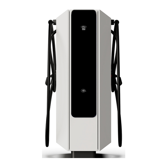
POWER ELECTRONICS INTRODUCTION Power Electronics’ NB 240 standalone manages both the power transformation and main control for the charge, and the user interface and connection with the EV at the same enclosure. The equipment integrates a built-in cable management system that allows five meters long charging cables without them dragging on the ground. -
Page 18: Equipment Overview
POWER ELECTRONICS NB 240 Equipment overview The following sections describe the different components of the EV charger. Charger The NB 240 series charger can be provided with two independent hoses with connectors for DC charging of electric vehicles with CCS-1, CCS-2 and CHAdeMO standards for DC. It can optionally include a type 2 socket for AC charging. - Page 19 NB 240 POWER ELECTRONICS Connectors The charger has up to three independent cable straight hoses with the standard connectors. The possibility of installing and combining the connectors depends on which regulations are applied in each country and the interest in offering different options to the users.
-
Page 20: Charging Process
POWER ELECTRONICS NB 240 AC socket type 2 Charging process The user must follow the instructions given below when performing a charging session: If the charger is available, activate the charging session from the display, RFID contact or mobile App (depending on available options). -
Page 21: Advanced Charge Functionality
NB 240 POWER ELECTRONICS Advanced charge functionality Smart Fleet Management (optional) This functionality has been designed to minimize the initial investment and operation costs. It is able to balance the power based on the number of charging posts in use. Therefore, the total power required to supply the total energy gets substantially reduced, representing a cost reduction in the electrical facility infrastructure and a cost saving due to a minor power contracted. -
Page 22: Power Retrofit (Optional)
POWER ELECTRONICS NB 240 Power retrofit (optional) The power retrofit uses modular technology It allows the NB 240 charger to be easily power-scalable adding power modules to support EV fleets growth or to follow the increase in EV market size over time. -
Page 23: Technical Characteristics
NB 240 POWER ELECTRONICS TECHNICAL CHARACTERISTICS Depending on the regulation to be followed, the equipment will fulfill different technical characteristics. Standalone NB 240 – IEC / UL NB2100H NB2400H NB1500H NB1800H NB2100U NB2400U NB1500U NB1800U REFERENCE NB150SH NB180SH NB210SH NB240SH... - Page 24 [2] Consult with Power Electronics for more information about the connector overload capability. [3] Consult with Power Electronics for further information Be aware that Power Electronics is not responsible for the charger's input power connection, nor its installation. TECHNICAL CHARACTERISTICS...
-
Page 25: Standalone Nb 240 - Iec / Ul Slim And Cooled Additional Dispenser
[3] Cooled connector only available with 1 simultaneous output. [4] Consult with Power Electronics for further information. Be aware that Power Electronics is not responsible for the additional dispenser’s input power connection. Please, refer to the corresponding Hardware and Installation Manual. -
Page 26: Dimensions And Weight
POWER ELECTRONICS NB 240 DIMENSIONS AND WEIGHT The dimensions, gravity center and the weight of the NB 240 equipment are detailed in this section. The right and front view, from left to right, are shown below: GENERAL DIMENSIONS 2000 1900 1.38... - Page 27 The front and left view, from left to right, are shown below: GRAVITY CENTER 449,5 37.92 13.62 17.70 The approximate weight for the NB 240 is 600 kg (1322.77 lb) For other equipment of the NB 240 range, consult Power Electronics. DIMENSIONS AND WEIGHT...
-
Page 28: Handling And Transportation
The equipment is delivered perfectly packed and checked. Upon receipt, inspect the equipment. In the event of damage to the equipment, notify the logistics agent and Power Electronics 902 40 20 70, (International +34 96 136 65 57), or your nearest agent within 24 hours of receipt. Verify that the goods received correspond to the delivery note, models and serial numbers. -
Page 29: Extended Storage
If you receive replacement parts with the product, please separate and store it in a safe place. NOTICE Waste disposal is customer’s responsibility, and it is not within Power Electronics’ scope. Handling and transportation CAUTION Follow the handling and transportation requirements described here. - Page 30 POWER ELECTRONICS NB 240 For maritime shipment, the equipment is packed assembled vertically, in a cardboard box and fixed on a pallet base with screws at four steel brackets. Externally the box is strapped and shrink-wrapped. In case of air shipment, the charger is shipped lying down in a wooden box.
- Page 31 Close the doors again by following the reverse procedure. NOTICE If the methods described here cannot be applied, please contact Power Electronics. It is the customer's responsibility to ensure unhindered access of vehicles to the final site or location, taking into account their movement and handling at the unloading site.
-
Page 32: Preparation For Installing The Equipment
POWER ELECTRONICS NB 240 PREPARATION FOR INSTALLING THE EQUIPMENT Site recommendations When deciding the location of the equipment and planning its installation, it is recommended to follow a series of guidelines derived from its characteristics. CAUTION To guarantee proper electrical installation, it is very important to comply with the bend radius of the cable. - Page 33 POWER ELECTRONICS Site basis Power Electronics recommends making a concrete foundation slab to support the charger. The support surface for the equipment must be perfectly level. The client is responsible for the correct dimensioning and construction of the foundation in accordance with current regulations.
-
Page 34: Minimum Working Distances
POWER ELECTRONICS NB 240 Minimum working distances CAUTION When installing the equipment, keep the minimum safety distances. Be aware of all the minimum insulation requirements established by the applicable electrical code, as well as the thermal, safety and accessibility requirements. The safety distances given in this section must not replace in any way the mandatory regulations of the country in which the equipment will be installed. -
Page 35: Hose Maneuverability
NB 240 POWER ELECTRONICS Hose maneuverability To ensure the adequate maneuverability of both hoses, when installing the equipment, note that the maximum effective hose length is A = 4,6 m (15.1 ft) or optionally 7,2 m (23.7 ft). The following figure (front view) shows an example of the cable range area in a parking lot where cars... -
Page 36: Anchoring Of The Equipment
POWER ELECTRONICS NB 240 Anchoring of the equipment NOTICE It is the customer’s responsibility to dimension correctly posts anchoring to the foundation, guaranteeing stability towards horizontal actions. The equipment must be anchored to a solid and leveled surface (slab), see slab recommendations at “Site... -
Page 37: Ventilation System
NB 240 POWER ELECTRONICS Ventilation system CAUTION Special care must be taken to ensure that there are no external elements near the air inlets and outlets that prevent proper ventilation of the equipment. The equipment has a forced ventilation system with an inlet located on the right side of the equipment (front view) and a hot air outlet on the opposite side. -
Page 38: Cable Access And Connections
Power, ground, auxiliary and communication cables are not included within Power Electronics’ scope. MATERIAL WITHIN CUSTOMER'S RESPONSIBILITY: The following cables and elements are not provided by Power Electronics, they are customer's responsibility. • AC input power cables and terminal lugs (as applicable). -
Page 39: Access
NB 240 POWER ELECTRONICS Access The power and communication cables can enter through the bottom part on the equipment. To access the lower part, remove the front and rear bezel, see "Anchoring of the equipment". The power and communication cables enter and exit through the lower part of the charger by using the following space. - Page 40 POWER ELECTRONICS NB 240 Cable access plate The following image shows the footprint view of the standard cable entry plate. It is composed of the power supply input wire (L1, L2 and L3), ground wire and the neutral wire (N). The plate is labeled with their identification letter so that, at the time of connection, the cables go directly to their plates, avoiding excessive crossings and twists.
-
Page 41: Connections
NB 240 POWER ELECTRONICS Connections This section details the input and output connections that must be performed in the equipment. There are several factors that can influence the choice of cable, including the distance between the distribution board and the charger, the maximum input current and the installation mode. - Page 42 POWER ELECTRONICS NB 240 The tables below show the recommended, minimum and maximum ground and neutral cable size for the NB 240 range equipment. Customer must choose the cables taking into consideration the minimum and maximum diameter, as well as the particularities of the project:...
- Page 43 NB 240 POWER ELECTRONICS The following figure shows the correct connection of the neutral (N), ground (PE) and a single power input connection (L1, L2 and L3): REF. ELEMENT Terminal lug M12 (1/2”) bolt Spring washer Fender washer Plate M12 (1/2”) nut In case of the double power supply input (L1, L2 and L3), the connections are as follows: REF.
- Page 44 POWER ELECTRONICS NB 240 The following image shows the suggested terminal dimensions: Two-holes terminal Single-hole terminal DIMENSION DIMENSION 1.26 1.26 44,5 1.75 Φ 0.55 200,2 7.88 Φ 0.55 The ground plate is made of tin-plated aluminum. The following recommendations must be taken into account for the correct ground connection: •...
- Page 45 NB 240 POWER ELECTRONICS DC output power connections Exit from charger: Cable size: The tables below show the recommended, minimum and maximum DC output power cable size for the NB 240 associated additional Dispensers. Customer must choose the cables taking into consideration...
- Page 46 POWER ELECTRONICS NB 240 Connection: The DC output power connections (DC+ / DC-, PE) are directly connected to the Nema 2-hole lug, as shown in the following image. For all power cables, there is the possibility to double the output, using separate connections on the corresponding access plates and cable glands.
- Page 47 NB 240 POWER ELECTRONICS • Once the cable is in the equipment's front part, remove the polycarbonate cover that encloses the terminals. • Connect the cable to the corresponding terminal as shown in the picture below. Communications connection Ethernet: For high level communications protocols.
- Page 48 POWER ELECTRONICS NB 240 • “Cable access Enter the cable inside the equipment through the cable gland. Refer to plate” section for further information. And, guide it to the frontal side of the charger as shown below. • Once the cable is at the front of the equipment: First, remove the polycarbonate cover from the AC and the side panels.
- Page 49 NB 240 POWER ELECTRONICS Once the cable gets to the side panel, make the corresponding connections: At the switch, in the case of Ethernet cable, or at the combiner board for optical fiber. O.F. WARNING Before opening any door, the equipment must be completely isolated, without any tension. Be sure to follow the insulation guidelines and all safety instructions indicated in the "Safety...
-
Page 50: Protections
POWER ELECTRONICS NB 240 PROTECTIONS The charger is equipped with multiple hardware protections. This section describes the different protections available in the equipment. Insulation monitoring The equipment has an insulation monitor to detect possible insulation faults in DC charge. Overcurrent and short circuit protection... - Page 51 NB 240 POWER ELECTRONICS If this optional is included, the auxiliary protection is replaced by a type A RCBO. Nominal Nominal Breaking Rated Type Curve current (I voltage (U capacity (kA) sensitivity (A) RCBO F + N 10 A 277 V...
-
Page 52: Interface
• Charger status indicator: It is displayed on the Power Electronics logo, located on the glass face of each charger. It shows the charger current status using a color code. -
Page 53: Communications
NB 240 POWER ELECTRONICS COMMUNICATIONS The equipment requires several communications to work and to interact with the charger or customers. There are three ways to connect the equipment to internet, through either Ethernet, 3G / 4G, or Wi-Fi, depending on whether the equipment is connected or not to an additional Dispenser: •... -
Page 54: Ethernet Communication
Moreover, there is an Ethernet connection to monitor and configure the parameters through the Power Electronics’ applications, commonly used by the back office. This use is mainly focused on maintenance and commissioning. Power Electronics recommends using CAT5e or CAT6 copper cable and RJ45 connector for these connections. Optical fiber communication Optical fiber is only required for power regulation between the equipment and the additional Dispenser. -
Page 55: 3G / 4G Communication
NB 240 POWER ELECTRONICS 3G / 4G communication 3G / 4G is only required for the equipment communications without / with the additional Dispenser when neither Ethernet nor Wi-Fi are used for internet connection. For communication via 3G / 4G insert a MicroSIM card into the indicated charger control card slot:... -
Page 56: Loto Procedure
POWER ELECTRONICS NB 240 LOTO PROCEDURE The aim of the lockout / tagout or LOTO procedure is to protect the user towards unintended reconnections and to avoid risks associated with the control of energy sources. This involves isolating, locking and tagging the dangerous energy sources to avoid accidents / incidents mainly derived from dangerous movements, unexpected energizations or stored energy discharges. -
Page 57: Equipment Statuses
NB 240 POWER ELECTRONICS Equipment statuses Before working with the equipment, it is convenient to define two possible statuses. NB 240 STATUSES • Proper state for carrying the power revision. • Equipment running (no action required from safe stop). STATUS 1 Check points for absence of voltage: No measuring in Status 1. -
Page 58: Loto Actions
The customer is the one who disconnects and locks the LV supply connections, all keys must to be stored in a locked box and Power Electronics will keep one of the opening keys. Once the equipment is stopped, wait until the different storage buses are discharged (4 or 5 min). - Page 59 NB 240 POWER ELECTRONICS CAUTION Auxiliary supply must be disconnected last and connected first when possible. Electric shock hazard. Auxiliary supply power layout is a characteristic of each plant and may vary from one installation to another. Check the latest electrical schematics of the plant and make sure no voltage is present by confirming with a multimeter.
-
Page 60: Check Points For Absence Of Voltage
POWER ELECTRONICS NB 240 Check points for absence of voltage Follow this procedure as last LOTO actions to reach status 2 for both NB 240 and the additional Dispenser, if included. See previous subsections. CHECK POINTS FOR ABSENCE OF VOLTAGE Wear the appropriate PPE based on the electrical arc studies and the risk assessment carried out by the customer. -
Page 61: Commissioning
POWER ELECTRONICS COMMISSIONING CAUTION Commissioning may only be carried out by personnel authorized by Power Electronics. Read these instructions and all safety recommendations carefully. Failure to do so could result in damage to the equipment and serious injury to personnel. - Page 62 POWER ELECTRONICS NB 240 Verify the selectivity of the external protections to the equipment and control parameters. Activate the equipment´s internal protections Provide power to the external power supply and verify boards and power source light up. Configure the communications.
-
Page 63: Safe Stop
NB 240 POWER ELECTRONICS SAFE STOP CAUTION The shutdown of the equipment must only be carried out by personnel qualified. Read these instructions and all safety recommendations carefully. Otherwise, the equipment could be damaged and seriously injured personnel. The instructions in this manual do not replace local or national regulations. It is the user's responsibility to comply with all safety standards that apply at the installation site. -
Page 64: Emergency Stop And Restart
POWER ELECTRONICS NB 240 EMERGENCY STOP AND RESTART The following steps must be taken to activate the emergency stop, and subsequent restart, of the equipment: Press the emergency stop pushbutton, located on the right side of the equipment. Verify that the reason for the hazard or emergency has been resolved. -
Page 65: Maintenance
NB 240 POWER ELECTRONICS MAINTENANCE The NB 240 charger has been developed based on a revolutionary design concept that significantly simplifies the tasks and reduces preventive and corrective maintenance times. Nonetheless, there are some actions and revisions required. Equipment statuses Before detailing the maintenance procedure, it is convenient to define 2 possible statuses to carry out the maintenance tasks. -
Page 66: Checklist
POWER ELECTRONICS NB 240 Checklist The list of tasks detailed below should be carried out annually on both the NB 240 and the additional Dispenser, if included. The time of each task is an estimate for NB 240. In case of having the optional additional Dispenser, the maintenance time will be doubled.
Need help?
Do you have a question about the Ford Pro Standalone NB 240 and is the answer not in the manual?
Questions and answers