
Subscribe to Our Youtube Channel
Related Manuals for Libelium MySignals SW

Summary of Contents for Libelium MySignals SW
- Page 1 MySignals SW eHealth and Medical IoT Development Platform (HW rev.0) Technical Guide...
-
Page 2: Table Of Contents
5.2.1. Register a device with a license ..................28 6.2. MySignals Mobile APP ........................29 5.2.2. Encryption and bonding .....................31 5.3. Libelium Smart Devices App ......................32 6. Data Access .......................... 33 6.1. MySignals Standalone Mode ......................33 6.1.1. Using Standalone Mode .....................34 6.2.1. - Page 3 7.3.1. Monitoring sensors ......................249 7.3.2. Sampling sensors ......................256 7.3.3. Selecting sensors ......................257 8. Updating Firmware ......................263 8.1. Libelium Smart Devices App ......................263 9. MySignals API's ........................267 9.1. Cloud API ............................267 9.1.1. Basic configuration......................267 9.1.2.
-
Page 4: Mysignals Software Development Platform
Failure to comply with the recommendations of use will entail the guarantee cancellation. Software: Update firmware version only using Libelium Smart Devices App . If a different Software is used, MySignals can • be damaged and can become unresponsive. This use will void the warranty. -
Page 5: Conditions Of Use
As specified in the Warranty document the client has 7 days from the day the order is received to detect any failure and report that to Libelium. Any other failure reported after these 7 days may not be considered under warranty. -
Page 6: General View
All the data gathered by MySignals is encrypted and sent to the user's private account at Libelium Cloud through WiFi or Bluetooth. Data can be stored in the Libelium Cloud or being sent to a third party Cloud Server.The data can be visualized in a tablet or smart phone with Android or iPhone Apps. - Page 7 General view Libelium offers an API for developers to access the information. The Cloud API allows to access to the user's private account and get the information previously stored to be visualized in a third party platform. You can find all the info at: http://www.my-signals.com...
-
Page 8: Specifications
NOTE: MySignals Software Development Platform is a hardware closed device. It is ready to be used as a web and mobile App's development platform with the sensors distributed by Libelium. If you want to integrate new sensors (wired, BLE, BT) or program... -
Page 9: Notes
Notes 3. Notes 3.1. Important notes 1º - As a new product line we are updating the firmware and mobile App’s every week so please: Update regularly the MySignals Firmware to the last version. Go to the section “MySignals Firmware” of the guide •... - Page 10 Notes 4º - MySignals includes a stick to navigate through the menu options of the touchscreen. Please use it for a correct function of the device interface. 5º - The Firmware of MySignals SW manages all the sensors at the same time and monitors the response of ...
- Page 11 Notes 6º - At any time you can Activate / Deactivate the sinchronization of the information being sent to your Cloud Account by just pressing the Cloud icon on the top right corner. 7º - How can I see values older than one month in my Cloud account? MySignals Cloud Web Service (section 5.2) allows currently to see the complete historical data of any of the users.
- Page 12 Notes 9º - In February 2017 we have released new Firmware, Apps and Cloud versions that allow to record continuous waves and send them to the Cloud (in Server Mode). You can record up to 30 seconds of the data measured in detail mode of ECG, EMG, Snore and Airflow.
- Page 13 Notes 12º - Connect the ECG Electrodes to the ECG sensor cables before placing them in the user body. 13º - The ECG signals need to be measured with the user lained back on the bed or stretcher. 14º - In order to keep the MySignals enclosure clean and without any mark we recommend to place it inside the plastic bag and put the chamois cloth provided or any other protector desired on top of it before closing the bag.
-
Page 14: Faq
- Can I use all the sensors at the same time? In the case of MySignals SW, yes you can. In the case of MySignals HW the Arduino processor is limited, so you can not manage all the sensors, wireless communication and others features at the same time. You should select a correct combination of the options available. - Page 15 Notes - Can I use my own sensors? In the case of MySignals HW we provide the sensor pinout. You can use it to integrate your own sensors. WiFi, BLE, and BT2.0 connectivity is available too in order to integrate new wireless sensors. -15- v2.9...
-
Page 16: Hardware
Hardware 4. Hardware Figure: Top view of MySignals Software Included on MySignals device: Micro-Controller Circuit • Power Supply Circuit • Sensor Circuits • Bluetooth Low Energy module • WiFi module • Jack Sensor Connectors • In order to keep the MySignals enclosure clean and without any mark we recommend to place it into the plastic bag and add on top the chamois cloth provided before closing the bag. -
Page 17: Electrical Data
Hardware 4.1. Electrical Data The MySignals Software can be powered by an external power supply. General power supply Operating Current Operating Voltage Input Voltage (recommended) 7-9 V Input Voltage (limit) 7-12 V Specific power supply DC Current per I/O Pin [Max] DC Current for 3.3V 1 A [Max]... - Page 18 Hardware You can see all the information about the power supply in the label included in MySignals device. Figure: Certification MySignals label Do not connect or disconnect any sensor or connector while MySignals is ON. MySignals can become unstable or unresponsive, and internal parts can be damaged.
-
Page 19: Usb Data Transfer
4.2. USB Data Transfer This connector is used to update code into MySignals with a male USB to male Mini USB cable provided by Libelium. Just connect one side of the cable to this connector, removing protection cap from MySignals and connect the other side to a PC to update a code. -
Page 20: Data Interface
Hardware 4.3. Data Interface Data can be visualized by 3 different modes: Standalone mode: using the basic graphic TFT Integrated in the device. • Mobile APP'S: using the native Android / iOS connectivity to send all the data to the smartphone. •... -
Page 21: Wireless Communications
Figure: Connectivity MySignals diagram The data gathered by MySignals is encrypted and sent to the developer’s private account at the Libelium Cloud. (Developers may use their own Cloud too to store the information. More info in the API section below). -
Page 22: Software
The MySignals Software Development Platform includes a high level firmware that control all the features of the device at the same time. 5.1.1. Version 1.0.1 – Release Notes First Beta of MySignals Software Development Platform Firmware. • Copyright (C) 2016 Libelium Comunicaciones Distribuidas S.L. • • http://www.libelium.com October 5, 2016 •... -
Page 23: Version 1.0.2 - Release Notes
Software 5.1.2. Version 1.0.2 – Release Notes MySignals Software Development Platform Firmware. • Copyright (C) 2016 Libelium Comunicaciones Distribuidas S.L. • • http://www.libelium.com October 5, 2016 • Issues are resolved since last release V0.0.X: Server frame time reduced to 10 seconds. -
Page 24: Version 1.0.4 - Release Notes
• Language selection in Standalone mode • 5.1.4. Version 1.0.4 – Release Notes MySignals Software Development Platform Firmware. • Copyright (C) 2016 Libelium Comunicaciones Distribuidas S.L. • • http://www.libelium.com December 7, 2016 • Issues are resolved since last release V0.0.X: TFT firmware updated. -
Page 25: Version 1.0.5 - Release Notes
Software 5.1.5. Version 1.0.5 – Release Notes MySignals Software Development Platform Firmware. • Copyright (C) 2016 Libelium Comunicaciones Distribuidas S.L. • • http://www.libelium.com January 23, 2017 • Issues are resolved since last release V0.0.X: Raw mode integrated in server mode in detail section. -
Page 26: Version 1.0.6 - Release Notes
Software 5.1.6. Version 1.0.6 – Release Notes MySignals Software Development Platform Firmware. • Copyright (C) 2016 Libelium Comunicaciones Distribuidas S.L. • • http://www.libelium.com February 20, 2017 • Issues are resolved since last release V0.0.X: Raw mode integrated in server mode in detail section. -
Page 27: Mysignals Mobile App
MySignals device will send data to the mobile App in case the BLE mode is enabled. In this case the App will upload the data to the Cloud. The App can also be used to navigate through the users history at the Libelium Cloud. -
Page 28: Register A Device With A License
Software 5.2.1. Register a device with a license This is a simple and internal process that took place on the mobile application. First of all make sure you have a valid cloud credentials because without these credential the user is not able to login on cloud or mobile application, among other cloud services. -
Page 29: Mysignals Mobile App
NOTE: The Firmware of MySignals SW manages all the sensors at the same time and monitors the response of the screen and the touchscreen. For this reason sometimes during the measurement of different sensor like blood pressure or other wireless sensors it will be able to perform one action at the same time, you have to wait it to finish before being able to navigate or interact with the screen again. - Page 30 Software After login, if you have already selected a MySignals device skip this paragraph, if not continue reading. If the user had not selected a MySignals device to connect, after login, a popup message will prompt with a list of available MySignals device to connect.
-
Page 31: Encryption And Bonding
3. MySignals APP starts a connection with MySignals SW • 4. MySignals APP request bonding • 5. Both nodes exchange keys: bonding key appear in MySignals SW TFT screen. • 6. Both nodes store keys for future usage • -31-... -
Page 32: Libelium Smart Devices App
It could be Program Files or simply the desktop, but the important thing is for the processing folder to be pulled out of that .zip file. Then double-click Mysignals_Updater.exe to start. The Mac OS X version is also a .zip file. Double-click it and drag the Libelium Smart Devices App icon to the •... -
Page 33: Data Access
MySignals App. Then if the Cloud option is enable, the data will be also transferred to the user's account at the Libelium Cloud. Server Connection Mode: MySignals uses the WiFi connectivity to send the data directly to the Libelium Cloud. •... -
Page 34: Using Standalone Mode
Data Access 6.1.1. Using Standalone Mode First of all power the device with the Libelium MySignals power supply. Figure: TFT intro image To access this mode you must leave unchecked both options in the setup menu: Bluetooth Connection or Server Connection. - Page 35 Data Access Then you will enter in “Select Sensors” screen where you must select all the sensors that you want to measure. Selected sensors are in blue color and unselected sensors are in gray color. Figure: TFT Select Sensor Once you have completed your selection you must click on “Data” button, which you can find at the left end of the bottom toolbar.
- Page 36 Data Access If you are interested in viewing all the information in one particular sensor simply you have to click on it to enter a detail sensor view. On this screen you can see a graph of one of the sensor values and all the detailed information on a list view.
- Page 37 Data Access You can use this new function in Server Mode using detail mode. Use the Record button in order to start a new record. Note that you will not see the wave in the screen during each record. You will see a message in the graph zone. Here you can see the duration of the record.
- Page 38 Data Access With the record finished you can choose between saving this record in the cloud or cancel it. You will see all the information about the upload to the cloud at the bottom of the screen (text message zone). -38- v2.9...
- Page 39 NOTE: The Firmware of MySignals SW manages all the sensors at the same time and monitors the response of the screen and the touchscreen. For this reason sometimes during the measurement of different sensor like blood pressure or other wireless sensors it will be able to perform one action at the same time, you have to wait it to finish before being able to navigate or interact with the screen again.
- Page 40 Data Access to settings application from your Android device and select Bluetooth section, there you can get the list of bonded devices, you can delete the desired application on that point. If the user deletes a bonded device in Android device then the bonded connection must be deleted on MySignals device too.
-
Page 41: Using Bluetooth Connection Mode
Data Access 6.2.1. Using Bluetooth Connection Mode Below and to avoid any connection problems we recommend restarting the Bluetooth on your device if you already had it previously activated. We recommend doing this every time you open the app again. In order to do this go to Settings in your device, then Bluetooth and turn it off and on. - Page 42 Data Access The first time you open the APP you will see some configuration screens: For information on how to create an account and activate your license please visit the point 5.2.1 of this guide. • An account can have one MySignals device. Then we must create a MySignals Manager profile to provide a list •...
- Page 43 Data Access The mobile application adds a new feature to warn the user when a new update is available. On the login screens will show a popup window with that takes the user to the stores to perform the update, the warning will show on each new release and it will be mandatory to update the mobile application to keep on using it.
- Page 44 Data Access There is also a new feature on the login screens, now the user can get messages to advice about the quota of his account or incorrect password among other messages. The feature can warn about many erratical situations, these are the common ones: Incorrect account password.
- Page 45 Data Access - Now we move to the next screen "Profile” and enter our Manager Profile personal info. Figure: APP profile - Go to the next screen “WiFi”. Here you will need to provide your WiFi SSID name and your WiFi password in order to transmit this information to the MySignals device (this way it will be able to connect to the WiFi AP directly).
- Page 46 Data Access - Once arrived to the last configuration screen, before doing anything here in the phone app, you must power on MySignals, select “Bluetooth Connection” on configuration screen and click “Start Monitoring” button. Figure: TFT BLE selected When you see “Not Connected” message on the screen and a gray Bluetooth icon on MySignals screen, you can click on “Search for MySignals”...
- Page 47 Data Access Figure: APP searching Select your MySignals device on the list. Now if the bluetooth connection is working well, you will have to enter in your phone the code that you will see in blue color figures in MySignals screen. If you are using Android please check your notification center if your phone doesn't ask you to enter the code automatically.
- Page 48 Data Access Figure: Bluetooth PIN - The next screen is “Sensors”, where you must select all the sensors that you want to measure. Selected sensors are in blue color and unselected sensors are in gray color. Figure: APP sensor selection -48- v2.9...
- Page 49 Data Access MySignals device will send data to application using two modes: In General mode the MySignals device will send all values for all sensors, this is used for main sensors screen • where we show a list of selected sensors by the user with its values. You can see in this screen a color code in the sensor logos: Green: It is a real- time value measured in MySignals Software •...
- Page 50 Data Access On bottom section from the graph view the are three buttons: Right and left arrow buttons lets you move the graph to right or left. In the middle position, there is a play/pause button to start or stop the carousel mode. By default and once the graph load ends, the graph animation plays automatically.
- Page 51 Data Access In “General mode” screen you will be able to see in one glance the main information of all sensors at once. The latest received sensor info will be green, the sensors with old received info will be orange and sensors that hasn't received info will be gray.
- Page 52 Data Access Figure: Cloud synchronization button Using the users section you are able to select and modify the user profile. Figure: APP user configuration -52- v2.9...
- Page 53 Data Access Or organize them in different departments. Figure: APP department sections Figure: APP department organization There are several basic configuration screens: language, profile, user…. Where you can change your basic configuration. -53- v2.9...
- Page 54 Data Access Figure: APP settings mode - You can logout and login with another mysignals account: Figure: APP settings login -54- v2.9...
- Page 55 Data Access - You can change the language of the application Figure: APP settings language -You can change the device MySignals connected to the APP. Figure: APP settings devices -55- v2.9...
- Page 56 Data Access There is available a extra configuration section in the TFT where you can see your configuration info active: WiFi, account, user… You can use the DELETE button in order to delete the spirometers measures stored in the sensor (it should be connected when you press it).
- Page 57 Data Access In the firmware version 1.0.5 of higher you can use the DELETE BONDINGS function in order to delete all the bluetooth connection information. Figure: Delete Bondings Function You can use the RESET FACTORY VALUES function to restore MySignals to the basic configuration. Figure: Factory reset Settings -57- v2.9...
-
Page 58: Installing To An Iphone
Data Access 6.2.2. Installing to an iPhone Installation: a) Download the application from App Store: Then double click on the icon, or right click and open with iTunes. • Inside iTunes, on the left panel, click on DEVICES->Your Device. • Select on the top “Apps”, and select Sync Apps. -
Page 59: Mysignals Cloud Application
(this is the same method used in bank transfers). NOTE: The Firmware of MySignals SW manages all the sensors at the same time and monitors the response of the screen and the touchscreen. For this reason sometimes during the measurement of different sensor like blood pressure or other wireless sensors it will be able to perform one action at the same time, you have to wait it to finish before being able to navigate or interact with the screen again. -
Page 60: Using Server Connection Mode (Wifi Mode)
Data Access 6.3.1. Using Server Connection Mode (WiFi mode) If you are interested in using this mode you first need to follow the steps in previous section “Bluetooth Connection mode” in order to transmit to MySignals all the required information to send the data to the server: database user and password, and your local WiFi name and password. - Page 61 Data Access Once you have completed your selection you must click on “Data” button, which you can find at the left end of the bottom toolbar. In “Data” screen you will be able to see in one glance the main information of all sensors at once. The selected sensors will be green and sensors are not selected in red.
- Page 62 MySignals Application will have an user account to login into the system, this account is important to make cloud call and store information. If the user does not have an account the user cannot use MySignals Application. To access to the Libelium Cloud using your web browser go to: https://cloud.libelium.com/MySignals/ For information on how to create an account and activate your license please visit the point 5.2.1 of this guide...
- Page 63 Data Access In each account you may have several user profiles. You can create, delete or modify your users. Figure: MySignals user When the user starts the MySignals Application for the first time and setup assistant prompts the user will be able to create a profile once the user logs in.
- Page 64 Data Access You can see all the data of each device or user in the user's data section. device or user in the User Data section. Figure: User Data MySignals Web -64- v2.9...
- Page 65 Data Access Using the Department, User or Device configuration sections you can create, configure or delete them. Figure: Department configuration MySignals Web Figure: User configuration MySignals Web -65- v2.9...
- Page 66 Data Access Figure: Device configuration MySignals Web You can configure too your personal profile. Figure: Personal profile MySignals Web Now you can select the member or device that you want monitor. -66- v2.9...
- Page 67 Data Access First of all choose the sensor that you want to visualize. You can use the fast access menu situated on the left side of the Web Server. Figure: Select user Then you can see the General Sensor page. MySignals Web Server will monitor all the parameters in General Mode where it only show numeric values.
- Page 68 Data Access Finally, you can go to detail mode for each sensor selected. Press in the logo of the sensor in General Mode if you want to see the graphical and numeric values of a specific sensor. Figure: Detail mode Web Server -68- v2.9...
- Page 69 Data Access Raw data viewer A new feature has been added allowing us to see the raw data, also known as wave signal, for the sensors: Airflow, ECG, EMG and Snore. The member detail page shows a general view of the last values received for the different sensors. Please select one of the following sensors in order to go to the sensor detail page: Airflow: (Respiratory rate) •...
- Page 70 Data Access Once in this page click the 'Wave Signal' tab. In the bottom right of the page there is a drop down selector with the available raw values sorted by date. Select one of this an you will see the wave that was recorded using the MySignals hardware. -70- v2.9...
- Page 71 Data Access In the bottom center there is a pagination control that you can use for navigating the wave, going ahead and backwards in the time-line. In the bottom left part of the page it's displayed the average value for bpm, ppm, cpm or spm for the entire period of the wave recorded.
-
Page 72: Sensor Detail Interface
Data Access 6.3.2. Sensor detail interface 6.3.2.1. General view The interface for viewing the stored measurements has the following elements. 1. Hour navigation: Shows the hours of the selected day. Green slots contain data and can be clicked to display its chart. - Page 73 Data Access 6.3.2.2. Sensors Detail view improvement The sensors “Detail view” enables access to the history of the information previously stored. You can visualize data by choosing the month, the day and the hour. In this view, you can interact with these three elements: Hour selector: the data visualization is divided in the 24 hours of the day.
-
Page 74: New Admin Dashboard
Data Access 6.3.3. New Admin Dashboard Now you can access to the Admin Dashboard to check the the global Database Storage, the Traffic I/O consumption and the API Calls (for the Dev Mode). License Usage Time: it shows the percentage of license duration consumed. •... -
Page 75: Plans For Data Storage
MySignals Kit including all the sensors on different users as each one can have its own profile. All the data is sent to the Libelium Cloud, so users do not need to set up their own servers. - Page 76 The developers plans are the best option for users who want to store the data gathered by MySignals in their own servers. This type of plans allow to use the Cloud API to read the information from the Libelium Cloud and write it in their own Cloud platforms.
-
Page 77: How To Get Mysignals Cloud Plans
6.3.6. Account creation In order to access to the MySignals web application is necessary to have SCM account and a valid license. SCM stands for “Services Cloud Manager”, and is Libelium's platform from where you can manage your devices an Cloud Services 1.- To create a free SCM account please fill this form and click in the validation email that you will receive:... -
Page 78: License Activation
Data Access 6.3.7. License activation The “Licenses” section gives control of the licenses for the SCM. Licenses enable services for your devices. The “My Licenses” panel lists the currently active licenses and the historic data of all the expired licenses. If you recently purchased a License, go to the “Get Licenses”... - Page 79 Data Access . License registration is done The MySignals Cloud Licenses activation process will be ready-to-use from February 27 in the “Get Licenses” panel. It is a 2-step procedure: enter a valid license activation code and confirm the action. Entering a Single Activation Code will register one license. A Group Activation Code will register all devices belonging to the Sales Order, but not the licenses it may contain.
- Page 80 Data Access The SCM will validate the activation code, displaying a visual confirmation. When the process is finished successfully, a message will show that the license has been correctly added to the “My Licenses” panel. If the process could not be finished correctly, a message will notify the error. For example, “invalid activation code: please check that the activation code you entered is valid”.
-
Page 81: Using A Third Party Cloud
Data Access 6.4. Using a third party Cloud Developers may migrate the information stored in the Libelium Cloud to a third party Cloud server easily using the API Cloud provided. -81- v2.9... -
Page 82: Sensors
Sensors 7. Sensors MySignals allows you to measure more than 15 different biometric parameters such as pulse, breath rate, oxygen in blood, electrocardiogram signals, blood pressure, muscle electromyography signals, glucose levels, galvanic skin response, lung capacity, snore waves, patient position, airflow and body scale parameters (weight, bone mass, body fat, muscle mass, body water, visceral fat, Basal Metabolic Rate and Body Mass Index). - Page 83 Sensors If the ID of your device is 109 of higher you are using the new model with this new feature. -83- v2.9...
-
Page 84: Wired Sensors
Sensors 7.1. Wired Sensors MySignals Software Development Platform can work with 11 different wired biometric sensors. MySignals has a new improved connection system. It is very easy-to-use jack-connectors method. Figure: MySignals Software Development Platform with Wired Sensors NOTE: All detail screen for sensors on Mobile applications were replaced for a completely new web detail on MySignals Cloud, if you click onto a sensor in iPhone or Android application you will get a popup message pointing the new MySignals Cloud, there you can enjoy the new features for each sensor detail. -
Page 85: Pulse And Oxygen In Blood (Spo2)
Sensors 7.1.1. Pulse and Oxygen in Blood (SPO2) 7.1.1.1. Sensor features Description: Pulse oximetry a noninvasive method of indicating the arterial oxygen saturation of functional hemoglobin. Oxygen saturation is defined as the measurement of the amount of oxygen dissolved in blood, based on the detection of Hemoglobin and Deoxyhemoglobin. - Page 86 Sensors 7.1.1.2. Connecting the sensor Connect the sensor in the SPO2 connector indicated in the MySignals Hardware board. The sensor cable have only one way of connection to prevent errors and make the connection easier. Use the mini-USB connector to link the SPO2 with the MySignals board, using the jack connector of the cable in this side.
- Page 87 Sensors 7.1.1.3. Examples of use Standalone Mode This is an example of sensor measuring in Standalone Mode. First of all select the sensor that you want to measure in the Select Sensors screen. Use the touchscreen pressing in the correct symbol. You can see the selected sensors logos in blue color. Figure: Selected sensor logo Then you can go to General Sensor screen using the left down corner logo.
- Page 88 Sensors MySignals APP This is an example of sensor viewing in MySignals APP Mode. First of all select the sensor that you want to measure in the Select Sensors screen. Use your smartphone touchscreen pressing in the correct symbol. You can see the selected sensors logos in blue color. Figure: Selected sensor logo APP Then you can go to General Sensor screen using the left down corner logo.
- Page 89 Sensors Figure: Detail mode -89- v2.9...
- Page 90 Sensors MySignals Web Server This is an example of sensor viewing in MySignals Web Server Mode. First of all choose the sensor that you want to visualize. You can use the fast menu situated in the left side of the Web Server.
- Page 91 Sensors Figure: General mode Web Server Finally, you can go to detail mode for each sensor selected. Press in the logo of the sensor in General Mode if you want to see the graphical and numeric values of a specific sensor. Figure: Detail mode Web Server -91- v2.9...
- Page 92 Sensors Raw data viewer A new feature has been added allowing us to see the raw data, also known as wave signal, for the sensors: Airflow, ECG, EMG and Snore. The member detail page shows a general view of the last values received for the different sensors. Please select one of the following sensors in order to go to the sensor detail page: Airflow: (Respiratory rate) •...
- Page 93 Sensors Once in this page click the 'Wave Signal' tab. In the bottom right of the page there is a drop down selector with the available raw values sorted by date. Select one of this an you will see the wave that was recorded using the MySignals hardware. -93- v2.9...
- Page 94 Sensors In the bottom center there is a pagination control that you can use for navigating the wave, going ahead and backwards in the time-line. In the bottom left part of the page it's displayed the average value for bpm, ppm, cpm or spm for the entire period of the wave recorded.
-
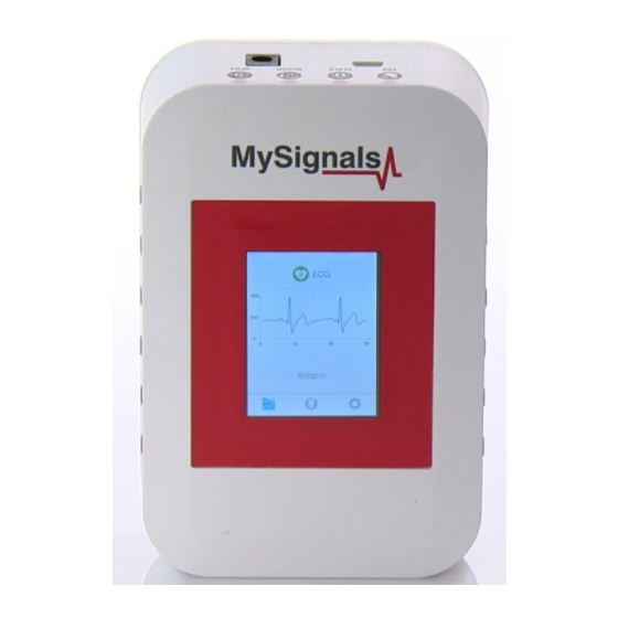
Page 95: Ecg
Sensors 7.1.2. ECG The Electrocardiogram Sensor (ECG) has grown to be one of the most commonly used medical tests in modern medicine. Its utility in the diagnosis of a myriad of cardiac pathologies ranging from myocardial ischemia and infarction to syncope and palpitations has been invaluable to clinicians for decades. The accuracy of the ECG depends on the condition being tested. - Page 96 Sensors Schematic representation of normal ECG Figure: ECG Signal representation Measurement: Parameter Unit Range Pulse rate BPM (Beats per minute) 0-200 bpm Electrocardiogram Volts 0-5V signal -96- v2.9...
- Page 97 Sensors 7.1.2.2. Connecting the sensor Connect the ECG Electrodes to the ECG sensor before placing them in the user body. The ECG signals need to be measured with the user lained back on the bed or stretcher. -97- v2.9...
- Page 98 Sensors Connect the jack sensor in the ECG connector indicated in the MySignals Hardware board. The sensor cable have only one way of connection to prevent errors and make the connection easier. Figure: MySignals Hardware Development Platform with ECG connected Connect the ECG lead to the electrodes.
- Page 99 Sensors Remove the protective plastic. You can use a specific conductive gel in order to improve the quality signal of the sensor. Figure: ECG electrodes removing protective plastic This sensor use disposable pre-gelled electrodes. These high quality disposable electrodes are to be used to measure EEG, ECG and EMG. They are to be used once and are very handy because of integrated gel.
- Page 100 Sensors NOTE: The sensor is designed to work on a user in supine position and under conditions of maximum relaxation. It is recommended not use this sensor in environments with excessive electromagnetic noise. -100- v2.9...
- Page 101 Sensors 7.1.2.3. Examples of use Standalone Mode This is an example of sensor measuring in Standalone Mode. First of all select the sensor that you want to measure in the Select Sensors screen. Use the touchscreen pressing in the correct symbol. You can see the selected sensors logos in blue color. Figure: Selected sensor logo Then you can go to General Sensor screen using the left down corner logo.
- Page 102 Sensors Figure: Detail mode In February 2017 we have released new Firmware, Apps and Cloud versions that allow to record continuous waves and send them to the Cloud (in Server Mode). You can record up to 30 seconds of the data measured in detail mode of ECG, EMG, Snore and Airflow.
- Page 103 Sensors You can use this new function in Server Mode using detail mode. Use the Record button in order to start a new record. Note that you will not see the wave in the screen during each record. You will see a message in the graph zone. Here you can see the duration of the record.
- Page 104 Sensors With the record finished you can choose between saving this record in the cloud or cancel it. You will see all the information about the upload to the cloud at the bottom of the screen (text message zone). -104- v2.9...
- Page 105 Sensors After a correct upload you will see the date of the file saved. Then you can see this new raw data file in the Web Server or in the Mobile APP. -105- v2.9...
- Page 106 Sensors MySignals APP This is an example of sensor viewing in MySignals APP Mode. First of all select the sensor that you want to measure in the Select Sensors screen. Use your smartphone touchscreen pressing in the correct symbol. You can see the selected sensors logos in blue color. Figure: Selected sensor logo APP Then you can go to General Sensor screen using the left down corner logo.
- Page 107 Sensors Finally, you can go to detail mode for each sensor selected. Press in the logo of the sensor in General Mode if you want to see the graphical and numeric values of a specific sensor. Figure: Detail mode There is a new tab on detail screen for ECG, EMG, Airflow and Snore sensors. This tab allows the user to display raw data recorded from MySignals device (in Server Mode).
- Page 108 Sensors On bottom section from the graph view the are three buttons: Right and left arrow buttons lets you move the graph to right or left. In the middle position, there is a play/pause button to start or stop the carousel mode. By default and once the graph load ends, the graph animation plays automatically.
- Page 109 Sensors MySignals Web Server This is an example of sensor viewing in MySignals Web Server Mode. First of all choose the sensor that you want to visualize. You can use the fast menu situated in the left side of the Web Server.
- Page 110 Sensors You can see in this screen a color code in the sensor logos: Green: It is a real- time value measured in MySignals Software • Orange: It is a old value measured in a previously connection of some time ago. •...
- Page 111 Sensors Raw data viewer A new feature has been added allowing us to see the raw data, also known as wave signal, for the sensors: Airflow, ECG, EMG and Snore. The member detail page shows a general view of the last values received for the different sensors. Please select one of the following sensors in order to go to the sensor detail page: Airflow: (Respiratory rate) •...
- Page 112 Sensors Once in this page click the 'Wave Signal' tab. In the bottom right of the page there is a dropdown selector with the available raw values sorted by date. Select one of this an you will see the wave that was recorded using the MySignals hardware. -112- v2.9...
- Page 113 Sensors In the bottom center there is a pagination control that you can use for navigating the wave, going ahead and backwards in the timeline. In the bottom left part of the page it's displayed the average value for bpm, ppm, cpm or spm for the entire period of the wave recorded.
-
Page 114: Airflow
Sensors 7.1.3. Airflow Anormal respiratory rates and changes in respiratory rate are a broad indicator of major physiological instability, and in many cases, respiratory rate is one of the earliest indicators of this instability. Therefore, it is critical to monitor respiratory rate as an indicator of patient status. AirFlow sensor can provide an early warning of hypoxemia and apnea. - Page 115 Sensors 7.1.3.2. Connecting the sensor Connect the sensor in the Airflow connector indicated in the MySignals Hardware board. The sensor cable include 2 pieces and it have only one way of connection to prevent errors and make the connection easier. Figure: MySignals Hardware Development Platform with Airflow connected The sensor integrate a extension cable with a “keyhole”...
- Page 116 Sensors The galvanic skin sensor has two contacts and it works like a ohmmeter measuring the resistance of the materials. Place your sensor as shown in the image below. MySignals Hardware Development Platform with Airflow situated in the user body After a few seconds you will get the values in the visualization method programmed.
- Page 117 Sensors 7.1.3.3. Examples of use Standalone Mode This is an example of sensor measuring in Standalone Mode. First of all select the sensor that you want to measure in the Select Sensors screen. Use the touchscreen pressing in the correct symbol. You can see the selected sensors logos in blue color. Figure: Selected sensor logo Then you can go to General Sensor screen using the left down corner logo.
- Page 118 Sensors Finally, you can go to detail mode for each sensor selected. Press in the logo of the sensor in General Mode if you want to see the graphical and numeric values of a specific sensor. Figure: Detail mode In February 2017 we have released new Firmware and App versions that allow to record continuous waves and send them to the Cloud only in server mode.
- Page 119 Sensors You can use this new function in Server Mode using detail mode. Use the Record button in order to start a new record. Note that you will not see the wave in the screen during each record. You will see a message in the graph zone. Here you can see the duration of the record.
- Page 120 Sensors With the record finished you can choose between saving this record in the cloud or cancel it. You will see all the information about the upload to the cloud at the bottom of the screen (text message zone). -120- v2.9...
- Page 121 Sensors After a correct upload you will see the date of the file saved. Then you can see this new raw data file in the Web Server or in the Mobile APP. -121- v2.9...
- Page 122 Sensors MySignals APP This is an example of sensor viewing in MySignals APP Mode. First of all select the sensor that you want to measure in the Select Sensors screen. Use your smartphone touchscreen pressing in the correct symbol. You can see the selected sensors logos in blue color. Figure: Selected sensor logo APP Then you can go to General Sensor screen using the left down corner logo.
- Page 123 Sensors Finally, you can go to detail mode for each sensor selected. Press in the logo of the sensor in General Mode if you want to see the graphical and numeric values of a specific sensor. Figure: Detail mode There is a new tab on detail screen for ECG, EMG, Airflow and Snore sensors. This tab allows the user to display raw data recorded from MySignals device (in Server Mode).
- Page 124 Sensors On bottom section from the graph view the are three buttons: Right and left arrow buttons lets you move the graph to right or left. In the middle position, there is a play/pause button to start or stop the carousel mode. By default and once the graph load ends, the graph animation plays automatically.
- Page 125 Sensors MySignals Web Server This is an example of sensor viewing in MySignals Web Server Mode. First of all choose the sensor that you want to visualize. You can use the fast menu situated in the left side of the Web Server.
- Page 126 Sensors You can see in this screen a color code in the sensor logos: Green: It is a real- time value measured in MySignals Software • Orange: It is a old value measured in a previously connection of some time ago. •...
- Page 127 Sensors Raw data viewer A new feature has been added allowing us to see the raw data, also known as wave signal, for the sensors: Airflow, ECG, EMG and Snore. The member detail page shows a general view of the last values received for the different sensors. Please select one of the following sensors in order to go to the sensor detail page: Airflow: (Respiratory rate) •...
- Page 128 Sensors Once in this page click the 'Wave Signal' tab. In the bottom right of the page there is a dropdown selector with the available raw values sorted by date. Select one of this an you will see the wave that was recorded using the MySignals hardware. -128- v2.9...
- Page 129 Sensors In the bottom center there is a pagination control that you can use for navigating the wave, going ahead and backwards in the timeline. In the bottom left part of the page it's displayed the average value for bpm, ppm, cpm or spm for the entire period of the wave recorded.
-
Page 130: Blood Pressure Monitor
Sensors 7.1.4. Blood Pressure Monitor Blood pressure is the pressure of the blood in the arteries as it is pumped around the body by the heart. When your heart beats, it contracts and pushes blood through the arteries to the rest of your body. This force creates pressure on the arteries. - Page 131 Sensors SPECIAL FEATURES: Automatic measurement of systolic, diastolic and pulse • 80 measurement results with time & date stored in the device • KEY SPECIFICATIONS Measurement method: Oscillometric system • Measuring range: Pressure 0-300 mmHg • Pulse 30~200 p/min • Measuring accuracy: Pressure≤±3 mmHg •...
- Page 132 Sensors 7.1.4.2. Connecting the sensor Connecting the sensor Connect the sensor in the Blood Pressure connector indicated in the MySignals Hardware board. The sensor cable have only one way of connection to prevent errors and make the connection easier. Use the mini-USB connector to link the Blood Pressure monitor with the MySignals board, using the normal jack connector (3.5mm) of the cable in this side.
- Page 133 Sensors Turn on the sphygmomanometer cuff (press ON button). The sensor will begin to make a measurement. In order to measure correctly is important to maintain the arm and the cuff in the correct position. Figure: Blood Pressure sensor ON button Do not make abrupt movements or the measure will be not reliable.
- Page 134 Sensors 7.1.4.3. Examples of use Standalone Mode This is an example of sensor measuring in Standalone Mode. First of all select the sensor that you want to measure in the Select Sensors screen. Use the touchscreen pressing in the correct symbol. You can see the selected sensors logos in blue color. Figure: Selected sensor logo Then you can go to General Sensor screen using the left down corner logo.
- Page 135 Sensors MySignals APP This is an example of sensor viewing in MySignals APP Mode. First of all select the sensor that you want to measure in the Select Sensors screen. Use your smartphone touchscreen pressing in the correct symbol. You can see the selected sensors logos in blue color. Figure: Selected sensor logo APP Then you can go to General Sensor screen using the left down corner logo.
- Page 136 Sensors Figure: Detail mode -136- v2.9...
- Page 137 Sensors MySignals Web Server This is an example of sensor viewing in MySignals Web Server Mode. First of all choose the sensor that you want to visualize. You can use the fast menu situated in the left side of the Web Server.
- Page 138 Sensors Figure: General mode Web Server Finally, you can go to detail mode for each sensor selected. Press in the logo of the sensor in General Mode if you want to see the graphical and numeric values of a specific sensor. Figure: Detail mode Web Server -138- v2.9...
-
Page 139: Glucometer
Sensors 7.1.5. Glucometer Despite widely variable intervals between meals or the occasional consumption of meals with a substantial carbohydrate load, human blood glucose levels tend to remain within the normal range. However, shortly after eating, the blood glucose level may rise, in non-diabetics, temporarily up to 7.8 mmol/L (140 mg/dL) or a bit more. 7.1.5.1. - Page 140 Sensors 7.1.5.2. Connecting the sensor Connect the sensor in the Glucometer connector indicated in the MySignals Hardware board. The sensor cable have only one way of connection to prevent errors and make the connection easier. Use the mini-jack connector (2.5mm) to link the Glucometer with the MySignals board, using the normal jack connector (3.5mm) of the cable in this side.
- Page 141 Sensors Clean the end of your index finger with rubbing alcohol before pricking it with an sterile needle or lancet. NOTE:The needles or lancets are not provided. Figure: Lancet glucometer method 1 Pierce your finger tip on the soft, fleshy pad and obtain a drop of blood. The type of drop of blood is determined by the type of strip you are using Figure: Lancet glucometer method 2 Place the drop of blood on or at the side of the strip.
- Page 142 Sensors Figure: Drop glucometer method 2 The glucometer will take a few moments to calculate the blood sugar reading. Figure: Glucometer measure The glucometer will store the value in the memory. -142- v2.9...
- Page 143 Sensors In order to extract the data from the glucometer to the Arduino, connect the cable as show in the picture. Figure: Cable connection You should view in the glucometer screen the message “P-C”, that indicates the correct connection. Figure: PC indication glucometer -143- v2.9...
- Page 144 Sensors The maximum recommended number of measures stored in the glucometer is 5. Please delete all the measures after it using the glucometer button. (press it several times and then use the M button) Figure: Configuration button in the glucometer You can turn off the device holding the M button during 3 seconds.
- Page 145 Sensors Setting time In order to use the date and time in each measure it is necesary to set correctly this parameters in the device. Figure: MySignals Hardware Development Platform with Glucometer DATE Set time information after insert new batteries. Use the button allocated in the batteries backpack in order to initialize the configuration of these parameters.
- Page 146 Sensors 7.1.5.3. Examples of use Standalone Mode This is an example of sensor measuring in Standalone Mode. First of all select the sensor that you want to measure in the Select Sensors screen. Use the touchscreen pressing in the correct symbol. You can see the selected sensors logos in blue color. Figure: Selected sensor logo Then you can go to General Sensor screen using the left down corner logo.
- Page 147 Sensors MySignals APP This is an example of sensor viewing in MySignals APP Mode. First of all select the sensor that you want to measure in the Select Sensors screen. Use your smartphone touchscreen pressing in the correct symbol. You can see the selected sensors logos in blue color. Figure: Selected sensor logo APP Then you can go to General Sensor screen using the left down corner logo.
- Page 148 Sensors Figure: Detail mode -148- v2.9...
- Page 149 Sensors MySignals Web Server This is an example of sensor viewing in MySignals Web Server Mode. First of all choose the sensor that you want to visualize. You can use the fast menu situated in the left side of the Web Server.
- Page 150 Sensors You can see in this screen a color code in the sensor logos: Green: It is a real- time value measured in MySignals Software • Orange: It is a old value measured in a previously connection of some time ago. •...
-
Page 151: Temperature
Sensors 7.1.6. Temperature Body temperature depends upon the place in the body at which the measurement is made, and the time of day and level of activity of the person. Different parts of the body have different temperatures. The commonly accepted average core body temperature (taken internally) is 37.0°C (98.6°F). In healthy adults, body temperature fluctuates about 0.5°C (0.9°F) throughout the day, with lower temperatures in the morning and higher temperatures in the late afternoon and evening, as the body's needs and activities change. - Page 152 Sensors 7.1.6.2. Connecting the sensor Connect the sensor in the Temperature connector indicated in the MySignals Hardware board. The sensor cable have only one way of connection to prevent errors and make the connection easier. Figure: MySignals Hardware Development Platform with Temperature connected Place your sensor as shown in the image below.
- Page 153 Sensors After a few seconds you will get the values in the visualization method programmed. NOTE: If an appropriate sensor data on the finger is not measured, it is necessary to use other more sensitive areas like the armpit. -153- v2.9...
- Page 154 Sensors 7.1.6.3. Examples of use Standalone Mode This is an example of sensor measuring in Standalone Mode. First of all select the sensor that you want to measure in the Select Sensors screen. Use the touchscreen pressing in the correct symbol. You can see the selected sensors logos in blue color. Figure: Selected sensor logo Then you can go to General Sensor screen using the left down corner logo.
- Page 155 Sensors MySignals APP This is an example of sensor viewing in MySignals APP Mode. First of all select the sensor that you want to measure in the Select Sensors screen. Use your smartphone touchscreen pressing in the correct symbol. You can see the selected sensors logos in blue color. Figure: Selected sensor logo APP Then you can go to General Sensor screen using the left down corner logo.
- Page 156 Sensors Figure: Detail mode -156- v2.9...
- Page 157 Sensors MySignals Web Server This is an example of sensor viewing in MySignals Web Server Mode. First of all choose the sensor that you want to visualize. You can use the fast menu situated in the left side of the Web Server.
- Page 158 Sensors You can see in this screen a color code in the sensor logos: Green: It is a real- time value measured in MySignals Software • Orange: It is a old value measured in a previously connection of some time ago. •...
-
Page 159: Emg
Sensors 7.1.7. EMG Electromyography (EMG) is an electrodiagnostic medicine technique for evaluating and recording the electrical activity produced by skeletal muscles. EMG is performed using an instrument called an electromyograph, to produce a record called an electromyogram. An electromyograph detects the electric potential generated by muscle cells when these cells are electrically or neurologically activated. - Page 160 Sensors Use your muscles to control any type of actuator (motors, servos, lights ...) Interact with the environment with your own muscles. This sensor comes with everything you need to start sensing muscle activity with your Arduino. The sensor needs to be connected to the specific EMG jack connector in MySignals board and it works with direct connector power supply.
- Page 161 Sensors 7.1.7.2. Connecting the sensor Connect the sensor in the EMG connector indicated in the MySignals Hardware board. The sensor cable have only one way of connection to prevent errors and make the connection easier. Figure: MySignals Hardware Development Platform with EMG connected Connect the EMG lead to the electrodes.
- Page 162 Sensors Figure: EMG electrodes removing protective plastic This sensor use disposable pre-gelled electrodes. These high quality disposable electrodes are to be used to measure EEG, ECG and EMG. They are to be used once and are very handy because of integrated gel. They adhere very well to the skin and are clean to use. The H124SG has a unique, patented pre-gelled adhesive side with non-irritating gel, especially developed to prevent allergic reactions.
- Page 163 Sensors 7.1.7.3. Examples of use Standalone Mode This is an example of sensor measuring in Standalone Mode. First of all select the sensor that you want to measure in the Select Sensors s. Use the touchscreen pressing in the correct symbol. You can see the selected sensors logos in blue color. Figure: Selected sensor logo Then you can go to General Sensor screen using the left down corner logo.
- Page 164 Sensors Finally, you can go to detail mode for each sensor selected. Press in the logo of the sensor in General Mode if you want to see the graphical and numeric values of a specific sensor. Figure: Detail mode In February 2017 we have released new Firmware and App versions that allow to record continuous waves and send them to the Cloud only in server mode.
- Page 165 Sensors You can use this new function in Server Mode using detail mode. Use the Record button in order to start a new record. Note that you will not see the wave in the screen during each record. You will see a message in the graph zone. Here you can see the duration of the record.
- Page 166 Sensors With the record finished you can choose between saving this record in the cloud or cancel it. You will see all the information about the upload to the cloud at the bottom of the screen (text message zone). -166- v2.9...
- Page 167 Sensors After a correct upload you will see the date of the file saved. Then you can see this new raw data file in the Web Server or in the Mobile APP. -167- v2.9...
- Page 168 Sensors MySignals APP This is an example of sensor viewing in MySignals APP Mode. First of all select the sensor that you want to measure in the Select Sensors screen. Use your smartphone touchscreen pressing in the correct symbol. You can see the selected sensors logos in blue color. Figure: Selected sensor logo APP Then you can go to General Sensor screen using the left down corner logo.
- Page 169 Sensors Figure: Detail mode There is a new tab on detail screen for ECG, EMG, Airflow and Snore sensors. This tab allows the user to display raw data recorded from MySignals device (in Server Mode). You can record until 30 seconds from MySignals device and show the recorded data on raw data tab, this tab is placed on the top right of the screen.
- Page 170 Sensors On bottom section from the graph view the are three buttons: Right and left arrow buttons lets you move the graph to right or left. In the middle position, there is a play/pause button to start or stop the carousel mode. By default and once the graph load ends, the graph animation plays automatically.
- Page 171 Sensors MySignals Web Server This is an example of sensor viewing in MySignals Web Server Mode. First of all choose the sensor that you want to visualize. You can use the fast menu situated in the left side of the Web Server.
- Page 172 Sensors You can see in this screen a color code in the sensor logos: Green: It is a real- time value measured in MySignals Software • Orange: It is a old value measured in a previously connection of some time ago. •...
- Page 173 Sensors Raw data viewer A new feature has been added allowing us to see the raw data, also known as wave signal, for the sensors: Airflow, ECG, EMG and Snore. The member detail page shows a general view of the last values received for the different sensors. Please select one of the following sensors in order to go to the sensor detail page: Airflow: (Respiratory rate) •...
- Page 174 Sensors Once in this page click the 'Wave Signal' tab. In the bottom right of the page there is a dropdown selector with the available raw values sorted by date. Select one of this an you will see the wave that was recorded using the MySignals hardware. -174- v2.9...
- Page 175 Sensors In the bottom center there is a pagination control that you can use for navigating the wave, going ahead and backwards in the timeline. In the bottom left part of the page it's displayed the average value for bpm, ppm, cpm or spm for the entire period of the wave recorded.
-
Page 176: Spirometer
Sensors 7.1.8. Spirometer Note: Spirometer Air Capacity Sensor is temporarily unavailable. Price already discounted from the total price of the Kit. Spirometry (meaning the measuring of breath) is the most common of the pulmonary function tests (PFTs), measuring lung function, specifically the amount (volume) and/or speed (flow) of air that can be inhaled and exhaled. - Page 177 Sensors Resistance to flow Back pressure @ 660L/min <0.11 KPa/sec Back pressure @ 900L/min <0.15 KPa/sec The sensor needs to be connected to the specific Spirometer jack connector in MySignals board and it works with internal batteries. Measurement: Parameter Unit Range Volume 0.01L~9.99L...
- Page 178 Sensors 7.1.8.2. Connecting the sensor Connect the sensor in the Spirometer connector indicated in the MySignals Hardware board. The sensor cable have only one way of connection to prevent errors and make the connection easier. Use the mini-USB connector to link the Spirometer with the MySignals board, using the normal jack connector (3.5mm) of the cable in this side. Before start using the glucometer we need one measure at least in the memory of the Spirometer.
- Page 179 Sensors Figure: Spirometer measure The glucometer will store the value in the memory. 3) In order to extract the data from the glucometer to the Arduino, connect the spirometer to Mysignals with the cable as show in the picture. Figure: Cable connection You should view in the glucometer screen a USB logo indication, that indicates the correct connection.
- Page 180 Sensors Figure: PC indication spirometer Deleting data stored The maximum recommended number of measures stored in the spirometer is 7. Please delete all the measures after it using the example code “spirometer_delete_measures” that you can find the the next sections. Powering the sensor It is very important to use batteries with more than 50% of charge in order to obten correctly the biometric information.
- Page 181 Sensors Setting time In order to use the date and time in each measure it is necesary to set correctly this parameters in the device. Figure: MySignals Hardware Development Platform with Spirometer DATE Set time information after insert new batteries. When you start with new batteries the sensor it initialize the configuration of these parameters.
- Page 182 Sensors 7.1.8.3. Examples of use Standalone Mode This is an example of sensor measuring in Standalone Mode. First of all select the sensor that you want to measure in the Select Sensors screen. Use the touchscreen pressing in the correct symbol. You can see the selected sensors logos in blue color. Figure: Selected sensor logo Then you can go to General Sensor screen using the left down corner logo.
- Page 183 Sensors MySignals APP This is an example of sensor viewing in MySignals APP Mode. First of all select the sensor that you want to measure in the Select Sensors screen. Use your smartphone touchscreen pressing in the correct symbol. You can see the selected sensors logos in blue color. Figure: Selected sensor logo APP Then you can go to General Sensor screen using the left down corner logo.
- Page 184 Sensors Figure: Detail mode -184- v2.9...
- Page 185 Sensors MySignals Web Server This is an example of sensor viewing in MySignals Web Server Mode. First of all choose the sensor that you want to visualize. You can use the fast menu situated in the left side of the Web Server.
- Page 186 Sensors You can see in this screen a color code in the sensor logos: Green: It is a real- time value measured in MySignals Software • Orange: It is a old value measured in a previously connection of some time ago. •...
-
Page 187: Gsr
Sensors 7.1.9. GSR Skin conductance, also known as galvanic skin response (GSR) is a method of measuring the electrical conductance of the skin, which varies with its moisture level. This is of interest because the sweat glands are controlled by the sympathetic nervous system, so moments of strong emotion, change the electrical resistance of the skin. - Page 188 Sensors 7.1.9.2. Connecting the sensor Connect the sensor in the GSR connector indicated in the MySignals Hardware board. The sensor cable have only one way of connection to prevent errors and make the connection easier. Figure: MySignals Hardware Development Platform with GSR connected Connect the GSR lead to the electrodes.
- Page 189 Sensors Place the electrodes as shown below. Figure: EMG position diagram The galvanic skin sensor has two contacts and it works like a ohmmeter measuring the resistance of the materials. Place your fingers in the metallic contacts and tighten the velcro as shown in the image below. Figure: MySignals Hardware Development Platform with GSR situated in the user body After a few seconds you will get the values in the visualization method programmed.
- Page 190 Sensors 7.1.9.3. Examples of use Standalone Mode This is an example of sensor measuring in Standalone Mode. First of all select the sensor that you want to measure in the Select Sensors screen. Use the touchscreen pressing in the correct symbol. You can see the selected sensors logos in blue color. Figure: Selected sensor logo Then you can go to General Sensor screen using the left down corner logo.
- Page 191 Sensors MySignals APP This is an example of sensor viewing in MySignals APP Mode. First of all select the sensor that you want to measure in the Select Sensors screen. Use your smartphone touchscreen pressing in the correct symbol. You can see the selected sensors logos in blue color. Figure: Selected sensor logo APP Then you can go to General Sensor screen using the left down corner logo.
- Page 192 Sensors Finally, you can go to detail mode for each sensor selected. Press in the logo of the sensor in General Mode if you want to see the graphical and numeric values of a specific sensor. Figure: Detail mode -192- v2.9...
- Page 193 Sensors MySignals Web Server This is an example of sensor viewing in MySignals Web Server Mode. First of all choose the sensor that you want to visualize. You can use the fast menu situated in the left side of the Web Server.
- Page 194 Sensors You can see in this screen a color code in the sensor logos: Green: It is a real- time value measured in MySignals Software • Orange: It is a old value measured in a previously connection of some time ago. •...
-
Page 195: Body Position
Sensors 7.1.10. Body Position Positions and movements made because of their relationships to particular diseases (i.e., sleep apnea and restless legs syndrome). Analyzing movements during sleep also helps in determining sleep quality and irregular sleeping patterns. The body position sensor could help also to detect fainting or falling of elderly people or persons with disabilities. - Page 196 Sensors 7.1.10.2. Connecting the sensor Connect the jack sensor in the Body Position connector indicated in the MySignals Hardware board. The sensor cable have only one way of connection to prevent errors and make the connection easier. Figure: MySignals Hardware Development Platform with Body Position connected Place the tape around the chest and the connector placed down Figure: MySignals Hardware Development Platform with Body Position situated in the user body After a few seconds you will get the values in the visualization method programmed.
- Page 197 Sensors 7.1.10.3. Examples of use Standalone Mode This is an example of sensor measuring in Standalone Mode. First of all select the sensor that you want to measure in the Select Sensors screen. Use the touchscreen pressing in the correct symbol. You can see the selected sensors logos in blue color. Figure: Selected sensor logo Then you can go to General Sensor screen using the left down corner logo.
- Page 198 Sensors MySignals APP This is an example of sensor viewing in MySignals APP Mode. First of all select the sensor that you want to measure in the Select Sensors screen. Use your smartphone touchscreen pressing in the correct symbol. You can see the selected sensors logos in blue color. Figure: Selected sensor logo APP Then you can go to General Sensor screen using the left down corner logo.
- Page 199 Sensors Figure: Detail mode -199- v2.9...
- Page 200 Sensors MySignals Web Server This is an example of sensor viewing in MySignals Web Server Mode. First of all choose the sensor that you want to visualize. You can use the fast menu situated in the left side of the Web Server.
- Page 201 Sensors You can see in this screen a color code in the sensor logos: Green: It is a real- time value measured in MySignals Software • Orange: It is a old value measured in a previously connection of some time ago. •...
-
Page 202: Snore
Sensors 7.1.11. Snore Snoring is a major symptom of obstructive sleep apnea (OSA). In most sleep studies, snoring is detected with a microphone. Since these studies analyze the acoustic properties of snoring, they need to acquire data at high sampling rates, so a large amount of data should be processed. Recently, several sleep studies have monitored snoring using a piezo snoring sensor. - Page 203 Sensors Vibration-type sensor unit: 1. With pretty good anti-noise performance • 2. Detachable acoustic tube design • 3. Translucent earbud, better for personal hygiene and discreet measurement • 4. Comfortable With high-quality flexible plastic clip • 5. Easy to be fixed on your desired place •...
- Page 204 Sensors 7.1.11.2. Connecting the sensor Connect the sensor in the snore double connector indicated in the MySignals Hardware board. The sensor cable have only one way of connection to prevent errors and make the connection easier. Figure: MySignals Software Development Platform with Snore connected Place the sensor in your neck as you can see in the next image.
- Page 205 Sensors 7.1.11.3. Examples of use Standalone Mode This is an example of sensor measuring in Standalone Mode. First of all select the sensor that you want to measure in the Select Sensors screen. Use the touchscreen pressing in the correct symbol. You can see the selected sensors logos in blue color. Figure: Selected sensor logo Then you can go to General Sensor screen using the left down corner logo.
- Page 206 Sensors Finally, you can go to detail mode for each sensor selected. Press in the logo of the sensor in General Mode if you want to see the graphical and numeric values of a specific sensor. Figure: Detail mode In February 2017 we have released new Firmware, Apps and Cloud versions that allow to record continuous waves and send them to the Cloud (in Server Mode).
- Page 207 Sensors You can use this new function in Server Mode using detail mode. Use the Record button in order to start a new record. Note that you will not see the wave in the screen during each record. You will see a message in the graph zone. Here you can see the duration of the record.
- Page 208 Sensors With the record finished you can choose between saving this record in the cloud or cancel it. You will see all the information about the upload to the cloud at the bottom of the screen (text message zone). -208- v2.9...
- Page 209 Sensors After a correct upload you will see the date of the file saved. Then you can see this new raw data file in the Web Server or in the Mobile APP. -209- v2.9...
- Page 210 Sensors MySignals APP This is an example of sensor viewing in MySignals APP Mode. First of all select the sensor that you want to measure in the Select Sensors screen. Use your smartphone touchscreen pressing in the correct symbol. You can see the selected sensors logos in blue color. Figure: Selected sensor logo APP Then you can go to General Sensor screen using the left down corner logo.
- Page 211 Sensors Figure: Detail mode There is a new tab on detail screen for ECG, EMG, Airflow and Snore sensors. This tab allows the user to display raw data recorded from MySignals device (in Server Mode). You can record until 30 seconds from MySignals device and show the recorded data on raw data tab, this tab is placed on the top right of the screen.
- Page 212 Sensors On bottom section from the graph view the are three buttons: Right and left arrow buttons lets you move the graph to right or left. In the middle position, there is a play/pause button to start or stop the carousel mode. By default and once the graph load ends, the graph animation plays automatically.
- Page 213 Sensors MySignals Web Server This is an example of sensor viewing in MySignals Web Server Mode. First of all choose the sensor that you want to visualize. fast menu situated in the left side of the Web Server. Choose an user. Figure: Select user Then you can see the General Sensor page.
- Page 214 Sensors Figure: General mode Web Server Finally, you can go to detail mode for each sensor selected. Press in the logo of the sensor in General Mode if you want to see the graphical and numeric values of a specific sensor. Figure: Detail mode Web Server -214- v2.9...
- Page 215 Sensors Raw data viewer A new feature has been added allowing us to see the raw data, also known as wave signal, for the sensors: Airflow, ECG, EMG and Snore. The member detail page shows a general view of the last values received for the different sensors. Please select one of the following sensors in order to go to the sensor detail page: Airflow: (Respiratory rate) •...
- Page 216 Sensors Once in this page click the 'Wave Signal' tab. In the bottom right of the page there is a dropdown selector with the available raw values sorted by date. Select one of this an you will see the wave that was recorded using the MySignals hardware. -216- v2.9...
- Page 217 Sensors In the bottom center there is a pagination control that you can use for navigating the wave, going ahead and backwards in the timeline. In the bottom left part of the page it's displayed the average value for bpm, ppm, cpm or spm for the entire period of the wave recorded.
-
Page 218: Wireless Sensors (Ble)
Sensors 7.2. Wireless Sensors (BLE) MySignals Hardware Development Platform can work with 4 different wireless biometric sensors using BLE connectivity. My Signals Glucometer (BLE) • My Signals Blood pressure monitor (BLE) • My Signals Pulsioximeter SPO2 (BLE) • My Signals Scale (BLE) •... - Page 219 Sensors NOTE: All detail screen for sensors on Mobile applications were replaced for a completely new web detail on MySignals Cloud, if you click onto a sensor in iPhone or Android application you will get a popup message pointing the new MySignals Cloud, there you can enjoy the new features for each sensor detail.
-
Page 220: Body Scale (Ble)
Sensors 7.2.1. Body Scale (BLE) Weighing scales (or weigh scales or scales) are devices to measure weight or calculate mass. Spring balances or spring scales measure weight (force) by balancing the force due to gravity against the force on a spring, whereas a balance or pair of scales using a balance beam compares masses by balancing the weight due to the mass of an object against the weight of a known mass or masses. - Page 221 Sensors 7.2.1.2. Connecting the sensor This sensor have not cable. This sensor send the data wirelessly to MySignals board. The device is designed to allow auto step on. The first time you use the scale please ignore the initial reading •...
- Page 222 Sensors The sensor will begin to make a measurement. In order to measure correctly is important to maintain body in the correct position. Wait until MySignals program indicate that it is connected with the BLE sensor. Figure: Body Scale measure finished Do not make abrupt movements or the measure will be not reliable.
- Page 223 Sensors 7.2.1.3. Examples of use Standalone Mode This is an example of sensor measuring in Standalone Mode. First of all select the sensor that you want to measure in the Select Sensors screen. Use the touchscreen pressing in the correct symbol. You can see the selected sensors logos in blue color. Figure: Selected sensor logo Then you can go to General Sensor screen using the left down corner logo.
- Page 224 Sensors MySignals Web Server This is an example of sensor viewing in MySignals Web Server Mode. First of all choose the sensor that you want to visualize. You can use the fast menu situated in the left side of the Web Server.
- Page 225 Sensors Then you can see the General Sensor page. MySignals Web Server will monitor all the parameters in General Mode where it only show numeric values. You can see in this screen a color code in the sensor logos: Green: It is a real- time value measured in MySignals Software •...
-
Page 226: Pulse And Oxygen In Blood Spo2 (Ble)
Sensors 7.2.2. Pulse and Oxygen in Blood SPO2 (BLE) 7.2.2.1. Sensor features Description: Pulse oximetry a noninvasive method of indicating the arterial oxygen saturation of functional hemoglobin. Oxygen saturation is defined as the measurement of the amount of oxygen dissolved in blood, based on the detection of Hemoglobin and Deoxyhemoglobin. - Page 227 Sensors 7.2.2.2. Connecting the sensor This sensor have not cable. This sensor send the data wirelessly to MySignals board. Place the SPO2 on your finger as shown in the image below. Figure: SPO2 connection diagram Turn on the SPO2 (press ON button). The sensor will begin to make a measurement. In order to measure correctly is important to maintain finger in the correct position.
- Page 228 Sensors The SPO2 will take a few moments to calculate the pulsioximeter reading and send them wirelessly Figure: MySignals Hardware Development Platform with SPO2 situated in the user body After a few seconds you will get the values in the visualization method programmed. -228- v2.9...
- Page 229 Sensors 7.2.2.3. Examples of use Standalone Mode This is an example of sensor measuring in Standalone Mode. First of all select the sensor that you want to measure in the Select Sensors screen. Use the touchscreen pressing in the correct symbol. You can see the selected sensors logos in blue color. Figure: Selected sensor logo Then you can go to General Sensor screen using the left down corner logo.
- Page 230 Sensors MySignals Web Server This is an example of sensor viewing in MySignals Web Server Mode. First of all choose the sensor that you want to visualize. You can use the fast menu situated in the left side of the Web Server.
- Page 231 Sensors You can see in this screen a color code in the sensor logos: Green: It is a real- time value measured in MySignals Software • Orange: It is a old value measured in a previously connection of some time ago. •...
-
Page 232: Blood Pressure Monitor (Ble)
Sensors 7.2.3. Blood Pressure Monitor (BLE) Blood pressure is the pressure of the blood in the arteries as it is pumped around the body by the heart. When your heart beats, it contracts and pushes blood through the arteries to the rest of your body. This force creates pressure on the arteries. - Page 233 Sensors KEY SPECIFICATIONS Measurement method: Oscillometric system • Measuring range: Pressure 0-300 mmHg • Pulse 30~200 p/min • Measuring accuracy: Pressure ≤ ±3 mmHg • Pulse ≤ 5% • Operating environment: Temperature 10-40ºC • Relative humidity ≤ 80% • The sensor works with internal rechargeable battery. Use the Blood pressure specific cable in order to charge the sensor connected to MySignals.
- Page 234 Sensors 7.2.3.2. Connecting the sensor Connecting the sensor This sensor have not cable. This sensor send the data wirelessly to MySignals board. Place the sphygmomanometer on your arm (biceps zone) as shown in the image below. Figure: Blood Pressure connection diagram Turn on the sphygmomanometer cuff (press ON button).
- Page 235 Sensors Figure: MySignals Hardware Development Platform with Blood Pressure situated in the user body After a few seconds you will get the values in the visualization method programmed. -235- v2.9...
- Page 236 Sensors 7.2.3.3. Examples of use Standalone Mode This is an example of sensor measuring in Standalone Mode. First of all select the sensor that you want to measure in the Select Sensors screen. Use the touchscreen pressing in the correct symbol. You can see the selected sensors logos in blue color. Figure: Selected sensor logo Then you can go to General Sensor screen using the left down corner logo.
- Page 237 Sensors MySignals Web Server This is an example of sensor viewing in MySignals Web Server Mode. First of all choose the sensor that you want to visualize. You can use the fast menu situated in the left side of the Web Server.
- Page 238 Sensors Then you can see the General Sensor page. MySignals Web Server will monitor all the parameters in General Mode where it only show numeric values. You can see in this screen a color code in the sensor logos: Green: It is a real- time value measured in MySignals Software •...
-
Page 239: Glucometer (Ble)
Sensors 7.2.4. Glucometer (BLE) Despite widely variable intervals between meals or the occasional consumption of meals with a substantial carbohydrate load, human blood glucose levels tend to remain within the normal range. However, shortly after eating, the blood glucose level may rise, in non-diabetics, temporarily up to 7.8 mmol/L (140 mg/dL) or a bit more. 7.2.4.1. - Page 240 Sensors 7.2.4.2. Connecting the sensor This sensor have not cable. This sensor send the data wirelessly to MySignals board. Place a test strip in the machine when the machine is ready. Watch the indicator for placing the blood to the strip. Once the test strip package is opened, it must be consumed within 3 months.
- Page 241 Sensors Figure: Lancet glucometer method 1 Pierce your finger tip on the soft, fleshy pad and obtain a drop of blood. The type of drop of blood is determined by the type of strip you are using Figure: Lancet glucometer method 2 Place the drop of blood on or at the side of the strip.
- Page 242 Sensors Figure: Drop glucometer method 2 The glucometer will take a few moments to calculate the blood sugar reading. Figure: Glucometer measure The glucometer send wirelessly the value to MySignals. -242- v2.9...
- Page 243 Sensors Figure: Diagram connection When the glucometer send all the information, turn off the device. -243- v2.9...
- Page 244 Sensors 7.2.4.3. Examples of use Standalone Mode This is an example of sensor measuring in Standalone Mode. First of all select the sensor that you want to measure in the Select Sensors screen. Use the touchscreen pressing in the correct symbol. You can see the selected sensors logos in blue color. Figure: Selected sensor logo Then you can go to General Sensor screen using the left down corner logo.
- Page 245 Sensors MySignals Web Server This is an example of sensor viewing in MySignals Web Server Mode. First of all choose the sensor that you want to visualize. You can use the fast menu situated in the left side of the Web Server.
- Page 246 Sensors Then you can see the General Sensor page. MySignals Web Server will monitor all the parameters in General Mode where it only show numeric values. You can see in this screen a color code in the sensor logos: Green: It is a real- time value measured in MySignals Software •...
-
Page 247: Bluetooth Sensors On Mobile Applications
Sensors 7.3. Bluetooth sensors on mobile applications NOTE: All detail screen for sensors on Mobile applications were replaced for a completely new web detail on MySignals Cloud, if you click onto a sensor in iPhone or Android application you will get a popup message pointing the new MySignals Cloud, there you can enjoy the new features for each sensor detail. - Page 248 Sensors Inside these application we make difference between two types of bluetooth sensors: Monitoring sensors: They give a continuos data on main data screen and inside the detail screen of each one. • Sampling sensors: They give a single measure each time and the user must connect with the application on •...
-
Page 249: Monitoring Sensors
Sensors 7.3.1. Monitoring sensors These set of sensors are bluetooth pulsioximeter, bluetooth temperature and bluetooth alarm. These three item have the same steps to connect them. Now we are going to describe how to connect each one and how to obtain data from each sensor with a set of simple steps. - Page 250 Sensors If the mobile application has established a previous connection, when the user taps on one monitoring sensors the application will try to connect the last used bluetooht sensor, but if this connection fail the application will show the new scan screen to discover the device again. There is no limit about number of connected bluetooth devices on iPhone but on Android these is a limitation of three bluetooth peripherals connected (plus MySignals device), this was made to provide the application a stable connection along all the lifecycle until the user quits the mobile application.
- Page 251 Sensors -251- v2.9...
- Page 252 Sensors If the user confirm the selection the aplpication will show again the sensor list screen and another confirmation message to warn the user about the new connection between the mobile application and the bluetoth sensor: -252- v2.9...
- Page 253 Sensors Each time the user want to disconnect from a monitoring type sensor, just toouch again on the blue lighted sensor and it will turn grey and dissapears from main data screen. These kind of sensors perform a reconnection periodically, then if the user has these sensors selected but the bluetooth device is turned off just wait until the application reconnects with the bluetooth sensor.
- Page 254 Sensors When the mobile applications receives a new data entry from a bluetooth sensor the icon will turn green, but if the mobile application does not have new data from the bluetooth sensor the icon will turn orange and the application will show the lasta value obtained.
- Page 255 Sensors On these version we introduce a new sensor, the panic alarm button, these button starts s sound and a buzz to warn people about a problem and also sends an alert message. As the detail screen shows, the user can send an email or sms to notify the user about a problem, also it is possible to set a custom message and a phone number as destination.
-
Page 256: Sampling Sensors
Sensors 7.3.2. Sampling sensors This set of bluetoth sensors isprovided by bluetooth blood pressure, bluetooth glucometer and bluetooth scale. As said with monitoring sensors, there is no limit about number of connected bluetooth devices on iPhone but on Android these is a limitation of three bluetooth peripherals connected (plus MySignals device), this was made to provide the application a stable connection along all the lifecycle until the user quits the mobile application. -
Page 257: Selecting Sensors
Sensors 7.3.3. Selecting sensors It is very easy to select these kind of sensors, just tap over each one and they will be selected and show up on main data screen. To deselect these sensors just tap again and the light icon will turn grey and will disappear form main data screen. - Page 258 Sensors The first time the button connect is pushed, the mobile application will show a new screen to select the bluetooth sensor, this screen will show only bluetooth sensors provided with MySignals. The following tries the application will establish a connection with the bluetooth sensor and in case the mobile application cannot establish it will show a new screen to discover bluetooth sensors.
- Page 259 Sensors After that the sensor starts measuring: -259- v2.9...
- Page 260 Sensors We introduce another new feature available on bluettoth blood pressure sensor. This screen allows the user to set the measure interval on blood pressure, this values start from 30 seconds to 1800 seconds. Blood pressure sensor will start measuring again after this value and it will loop until the user exits from detail screen or turns off the bluetooth device.
- Page 261 Sensors If you choose”Make new measurement” you will start a little wizard that shows how to perform a measure, this wizard required a 2-steo setup: first one, “make sure that the scale is turned off “and second “step on the scale”. Sometimes, when the scale is turned off and the user steps on again, the sensor scale can display a not accurate weight, in this case you should step off the scale until it shows zero weight, then you can step on again to perform the measure.
- Page 262 Sensors When the scale connects with MySignals applciations, the blue button labeled as “Measure” turn green. After that wait a moment until the new measure is received from the scale sensor into the application, as a result the application will let you know when the process has finished. -262- v2.9...
-
Page 263: Updating Firmware
First of all and before installing anything, users have to take into account the platform where the application is going to be installed. To install the Libelium Smart Devices App, it is compulsory to have installed the JDK 1.7 at least. - Page 264 Users have to connect the device to the computer where the Smart Devices App is installed using the USB cable provided. Now open Libelium Smart Devices App . If you do not have Libelium Smart Devices App already installed in your PC, then go to the Development section of Libelium website to download it.
- Page 265 Updating Firmware Step 4: USB setting Select the corresponding serial port by going to tools/serial port. If you are unable to see the proper USB port maybe you should install the latest FTDI drivers on your PC. Then, refresh the “USB settings” block which is in the middle part of the tab, clicking in “refresh”...
- Page 266 Updating Firmware Step 7: Optional – Deleting firmware You can also delete the downloaded firmware marking the check from the list and then clicking on “Delete checked” button. Figure: Delete option WARNING: DO NOT UNPLUG MYSIGNALS WHILE IT IS BEING UPGRADED OR IT MAY BE RENDERED USELESS! (THIS CASE IS NOT COVERED BY THE WARRANTY) -266- v2.9...
-
Page 267: Mysignals Api's
9. MySignals API's 9.1. Cloud API Libelium MySignal comes with a Cloud API that allows us to read data from our account. We can see a list our members and read the values measured for a user by MySignal. This data available in this RESTful API can be used by the customer to create new developments. - Page 268 MySignals API's Method 1: Login Click over '/auth/login', fill the form with your email and password and click 'Try it out!'. If you provided the right data you should see something like this: Figure: API login The response body contains the token that you should use to access to your data in the following steps. Click 'Authorize', write 'Bearer <your token>' and click authorize.
- Page 269 MySignals API's Method 2: Get list of your members Click in '/members' section and then “Try it out!” button. You should see a list with your members. I you don't see it please make sure that your followed all the instructions of the previous step (Login) Figure: API members list Method 3: Get the sensor values of a member Click '/values' section and fill the parameters as in the picture.
- Page 270 MySignals API's The previous method requires specifiying the sensor_id. Alternatively there is another method that allows to request all the last values registered for all the sensors. Click '/values/last_member_data/' section and fill the parameters as in the picture. Then click “Try it out!” button. -270- v2.9...
- Page 271 MySignals API's Available values for sensor_id are: sensor_id name units position Body position 1 supine, 2 left, 3 right, 4 prone, 5 stand or sit, 6 non- defined position_x X axis acc position_y X axis acc position_z X axis acc temp Temperature º...
- Page 272 MySignals API's Method 4: Get a list of sensor raw data Click '/raws' section and fill the parameters as in the picture. Then click “Try it out!” button. Available values for sensor_id are: sensor_id name airflow_raw Airflow Wave Signal ecg_raw ECG Wave Signal emg_raw EMG Wave Signal...
- Page 273 MySignals API's Method 5: Get detail of sensor raw data Click '/raws/{id}' section and fill the parameters as in the picture. Then click “Try it out!” button. -273- v2.9...
-
Page 274: Php Example
This will log you in the system, get a list of your members and get the latest 5 temperature values of one of your users. Copyright (C) 2016 Libelium Comunicaciones Distribuidas S.L. http://www.libelium.com This program is distributed WITHOUT ANY WARRANTY; without even the implied warranty of MERCHANTABILITY or FITNESS FOR A PARTICULAR PURPOSE. - Page 275 MySignals API's //2.- Get mymembers $response_members = \Httpful\Request::get($api_base . '/members') ->addHeaders($api_headers) ->send(); echo "2.- Get my members: <br><br><pre>".json_encode($response_members->body, JSON_PRETTY_ PRINT)."</pre><hr><br>"; //3.- Get values from the first of my members if(count($response_members->body->data) >= 1){ $member_id = $response_members->body->data[0]->id; $parameters = [ 'member_id' => $member_id, 'sensor_id' =>...
-
Page 276: Documentation Changelog
Documentation Changelog 10. Documentation Changelog Version 0.0: Basic documentation generated for MySignals Software Development Platform • -276- v2.9... -
Page 277: Certifications
Certifications 11. Certifications My Signails SW is the first eHealth development platform to be fully certified. The user will benefit from a ready- to-work platform which is prepared and market-ready for the main regions on the world: CE (Europe) • FCC (USA) •... -
Page 278: Maintenance
Maintenance 12. Maintenance In this section, the term “MySignals” encompasses both the MySignals device itself as well as its sensors and • extra components. Take care when handling MySignals, do not let it fall, knock it or move it suddenly. •... -
Page 279: Disposal And Recycling
Disposal and recycling 13. Disposal and recycling In this section, the term “MySignals” encompasses both the MySignals device itself as well as its sensors and • extra components. When MySignals reaches the end of its useful life, it must be taken to an electronic equipment recycling point. •...
Need help?
Do you have a question about the MySignals SW and is the answer not in the manual?
Questions and answers